Mesh modification and UV problem
Hello Unity Community, today I come here seeking an answer to a problem I'm having with one of my projects.
Simply put, I'm trying to slice any convex object in half using a plane. The problem isn't with the slicing, its actually to do with generating new UV coordinates for the sliced mesh.
These are the steps I'm going through at the moment.
1) Grab a triangle from the original mesh, grab the UV coordinates that belong to the vertices.
2) Test against the plane, if no intersection, determine if its on the left or right side of plane, add the triangle as is to the new mesh with original UV coordinates.
3) if intersection is detected, grab the intersection points, which should be a maximum of 2 (only slicing with one plane)
4) triangulate the points using a convex hull algorithm, should yield either 1 or 2 triangles for 4 points.
5) using Barycentric coordinates of the original triangle, generate the new UV coordinates and add them to the mesh, perform same operation for the left/right hand side sliced meshes.
The primary problem I'm having is with step 5. There is severe inconsistency with the generated UV's, and I've spent more than a week testing my google-fu skills to try and fix the problem.
I'm going to share some code, mainly the calculation with the barycentric coordinates which i've used successfully in another project, so it should work as is.
 // compute the barycentric coordinates of triangle a-b-c in regards to point p and store result in references u-v-w respectively
 public static void barycentric(Vector3 a, Vector3 b, Vector3 c, Vector3 p, ref float u, ref float v, ref float w) {
     Vector3 m = Vector3.Cross(b - a, c - a);

     float nu;
     float nv;
     float ood;

     float x = Mathf.Abs(m.x);
     float y = Mathf.Abs(m.y);
     float z = Mathf.Abs(m.z);

     // compute areas of plane with largest projections
     if (x >= y && x >= z) {
         // area of PBC in yz plane
         nu = triArea2D(p.y, p.z, b.y, b.z, c.y, c.z);
         // area of PCA in yz plane
         nv = triArea2D(p.y, p.z, c.y, c.z, a.y, a.z);
         // 1/2*area of ABC in yz plane
         ood = 1.0f / m.x;
     }
     else if (y >= x && y >= z) {
         // project in xz plane
         nu = triArea2D(p.x, p.z, b.x, b.z, c.x, c.z);
         nv = triArea2D(p.x, p.z, c.x, c.z, a.x, a.z);
         ood = 1.0f / -m.y;
     }
     else {
         // project in xy plane
         nu = triArea2D(p.x, p.y, b.x, b.y, c.x, c.y);
         nv = triArea2D(p.x, p.y, c.x, c.y, a.x, a.y);
         ood = 1.0f / m.z;
     }

     u = nu * ood;
     v = nv * ood;
     w = 1.0f - u - v;
 }
and of course the triArea2D function
 public static float triArea2D(float x1, float y1, float x2, float y2, float x3, float y3) {
     return (x1 - x2) * (y2 - y3) - (x2 - x3) * (y1 - y2);
 }
this is where newVertexUV = u oldUVA + v oldUVB + w * oldUVC
Below is some screenshot of the problem I'm having
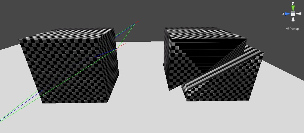
And an even more severe defect, when I slice at a slightly different angle
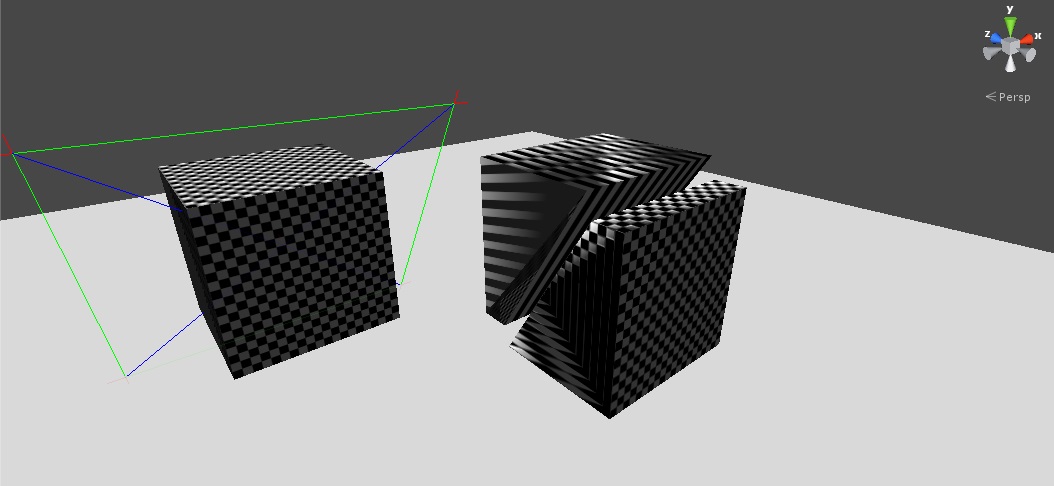
And this is the end of my question, I am officially stuck and have exhausted my google-fu skills. Does anyone know how or why the UV's are not generated properly using the technique above? could the order of triangles actually play a role? Thank you in advance.
Hmm, your barycentric calculation seems a bit strange to me ;) $$anonymous$$aybe try this one since i've tested it and returns correct values. Have you debugged your coordinates?
I've tried many versions, the one above is straight from the book "Real Time Collision Detection" by Christer Ericson, I also rely on it to re-triangulate the cut triangles by checking the sign of the coordinates, u+v+w is also equal to 1 or 0.999999f.
Uhm, of course u+v+w is 1 because of
w = 1.0f - u - v;
;) You should check the values itself. All should be 0
The barycentric coordinates are working as expected. I've also tried this function which yields the same results.
 public static void barycentricSign(Vector3 a, Vector3 b, Vector3 c, Vector3 p, ref float u, ref float v, ref float w) {
     Vector3 f1 = a - p;
     Vector3 f2 = b - p;
     Vector3 f3 = c - p;

     Vector3 va = Vector3.Cross(a - b, a - c);
     Vector3 va1 = Vector3.Cross(f2, f3);
     Vector3 va2 = Vector3.Cross(f3, f1);
     Vector3 va3 = Vector3.Cross(f1, f2);

     float area = va.magnitude;

     u = va1.magnitude / area * $$anonymous$$athf.Sign(Vector3.Dot(va, va1));
     v = va2.magnitude / area * $$anonymous$$athf.Sign(Vector3.Dot(va, va2));
     w = va3.magnitude / area * $$anonymous$$athf.Sign(Vector3.Dot(va, va3));
 }
Unfortunately the solution you posted only works with Vector2 types. 3D needs to be projected =]
Yes, you're right ;) I didn't think of it. However Barycentric coordinates always need to be in the same plane. Since you calculate the position of the new vertices your self you can simply use the distribution between the two original vartices.
So if A and B are the two vertices of the line you're going to split, just calculate:
 AB = B-A;
 AP = P-A;
 u = AP.magnitude / AB.magnitude
 v = 1-u;

 uv = UVA*v + UVB*u
I managed to find the answer, which may seem to be quite obvious. What I failed to mention above is that I attempt to conserve memory by sharing vertices in the new generated mesh, unfortunately this will not do. The problem here is the vertex sharing, and that's what is messing up the UV's.
Note to self in future, when generating your own UV coordinates, its probably better to have duplicate vertices, even though two vertices can be in same position, they may require different UV coordinates.
Hopefully this helps anyone who will come across a similar problem.
