Wayback Machinekoobas.hobune.stream
May JUN Jul
Previous capture 12 Next capture
2021 2022 2023
1 capture
12 Jun 22 - 12 Jun 22
sparklines
Close Help
  • Products
  • Solutions
  • Made with Unity
  • Learning
  • Support & Services
  • Community
  • Asset Store
  • Get Unity

UNITY ACCOUNT

You need a Unity Account to shop in the Online and Asset Stores, participate in the Unity Community and manage your license portfolio. Login Create account
  • Blog
  • Forums
  • Answers
  • Evangelists
  • User Groups
  • Beta Program
  • Advisory Panel

Navigation

  • Home
  • Products
  • Solutions
  • Made with Unity
  • Learning
  • Support & Services
  • Community
    • Blog
    • Forums
    • Answers
    • Evangelists
    • User Groups
    • Beta Program
    • Advisory Panel

Unity account

You need a Unity Account to shop in the Online and Asset Stores, participate in the Unity Community and manage your license portfolio. Login Create account

Language

  • Chinese
  • Spanish
  • Japanese
  • Korean
  • Portuguese
  • Ask a question
  • Spaces
    • Default
    • Help Room
    • META
    • Moderators
    • Topics
    • Questions
    • Users
    • Badges
  • Home /
avatar image
1
Question by gonzalitosk8 · Aug 07, 2019 at 04:12 PM · meshpathnormalsprocedural meshtangents

how to calculate this?

Hi group, I'm looking for a way to do something similar to this video: https://www.youtube.com/watch?v=3lMC3f-Khso

I need to calculate the tangent to update the position of the vertices, maintaining the width of the path, but I do not understand how to do it!

I leave the code in case someone wants to improve it, since it has an error, which is delayed in assigning the triangles to the last point added ...

I also leave a picture of how it looks todayalt text

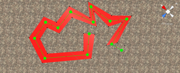
 public void GenMesh(){
 
         m = new Mesh();
         road.gameObject.GetComponent<MeshFilter> ().sharedMesh = m
         m.vertices = verts.ToArray ();
         verts.Clear();
 
         int count = nodes.Count;
         for (int i = 0; i < count; i++)
         {
             dir = Vector3.zero;
 
             if (i > 0)
                 dir += (nodes[i] - nodes[i - 1]).normalized;
             if (i < count-1)
                 dir += (nodes[i + 1] - nodes[i]).normalized;
             if (dir.sqrMagnitude > 0)
                 dir = dir.normalized;
             
             perpendicularDirection = new Vector3(-dir.z,0, dir.x);
             verts.Add (nodes[i] + perpendicularDirection * width);
             verts.Add (nodes[i] + perpendicularDirection * -width);
             norms.Add (Vector3.up);
             norms.Add (Vector3.up);
 
             if (Vector3.Distance (nodes [i], mousepos) < 0.7f) {
                 road.isOverObject = true;
             } else {
                 road.isOverObject = false;
             }
         }
         List<int> tris = new List<int> ();
         //Changed i+=3 to i++
         for(int i = 0; i < m.vertices.Length-3; i++){
             tris.Add(i+2);
             tris.Add(i+1);
             tris.Add(i);
             tris.Add(i+3);
             tris.Add(i+1);
             tris.Add(i+2);
         }
         m.triangles = tris.ToArray ();
         m.name = "pathMesh";
         HandleUtility.Repaint ();
     }


aroad.png (471.6 kB)
Comment
Add comment
10 |3000 characters needed characters left characters exceeded
▼
  • Viewable by all users
  • Viewable by moderators
  • Viewable by moderators and the original poster
  • Advanced visibility
Viewable by all users

2 Replies

· Add your reply
  • Sort: 
avatar image
1

Answer by Pakillottk · Aug 07, 2019 at 06:01 PM

Hi. Well, if you want to give a fixed width to the road you only need to make two polylines parallel to the main one (in fact, that how real roads usually work). So to do that, assuming that you only have straight lines (in real life, roads are usally made by: lines, arcs and clothoids) you only need to do this:

from 1 to n-1 vertices:

  1. pick vertex i

  2. pick vertex i+1

  3. find out angle between them (this is usually called azimuth, in topography)

  4. add 90 degs to the angle to find the left side (simply use the circle equation knowing that the radius is the road width and the center is vertex i)

  5. subtract 90 degs to the angle to find the right side (simply use the circle equation knowing that the radius is the road width and the center is vertex i)

  6. for the last vertex, you simply use the direction from the original polyline and add the length of the last segment to the parallel n-1 vertex

And with that you'll have a fixed width in each segment.

Also, I'd like to point out: what you are modelling is actually called the Horizontal Alignment of the road. If you are planning on having heights, modelling slopes and so on you'll need to model the Vertical Alignment also. That a very interesting excercise, because that's modelled almost entirely by circular arcs and parabolic arcs, so generating a 3D polyline with both of the alignments with the optimal number of points is a bit challenging.

Comment
Add comment · Share
10 |3000 characters needed characters left characters exceeded
▼
  • Viewable by all users
  • Viewable by moderators
  • Viewable by moderators and the original poster
  • Advanced visibility
Viewable by all users
avatar image
0

Answer by gonzalitosk8 · Aug 08, 2019 at 12:14 AM

This is what I am looking for! but I still don't understand how to apply the dot product for this escuacion ..

Can i change vector3.dot to vector3.Angle? will it be the same?

https://forum.libcinder.org/topic/smooth-thick-lines-using-geometry-shader

Comment
Add comment · Show 1 · Share
10 |3000 characters needed characters left characters exceeded
▼
  • Viewable by all users
  • Viewable by moderators
  • Viewable by moderators and the original poster
  • Advanced visibility
Viewable by all users
avatar image Bunny83 · Aug 08, 2019 at 01:09 AM 0
Share

What do you mean you don't understand how to apply the Dot product? The post has a quite clear explanation and sample code for everything. And no, you can not use Vector3.Angle. The dot product actually projects the miter line onto the normal of one of your segments. The steeper the angle the smaller the result. Since the thickness is divided by the projected distance the line will get longer which is the correct behaviour.


Your "perpendicularDirection" is the actual miter line. You did not yet calculate any normal of any of the two segments. You can probably do this:

 Vector3 dir = new Vector3();
 Vector3 norm = new Vector3();;
 if (i > 0) {
     norm = (nodes[i] - nodes[i - 1]).normalized;
     dir += norm;
 }
 if (i < count-1){
     norm = (nodes[i + 1] - nodes[i]).normalized;
     dir += norm;
 }
 
 if (dir.sqr$$anonymous$$agnitude > 0)
     dir = dir.normalized;
 norm = new Vector3(-norm.z, 0, norm.x);
 perpendicularDirection = new Vector3(-dir.z,0, dir.x);
 float length = width / $$anonymous$$athf.Abs(Vector3.Dot(perpendicularDirection, norm));
 verts.Add (nodes[i] + perpendicularDirection * length);
 verts.Add (nodes[i] + perpendicularDirection * -length);

So "norm" will actually hold one of the line segment normals. Which one is irrelevant since the miter line is the bisector so the angle between the miter line and the two segment normals is the same.

This code is untested,

Your answer

Hint: You can notify a user about this post by typing @username

Up to 2 attachments (including images) can be used with a maximum of 524.3 kB each and 1.0 MB total.

Follow this Question

Answers Answers and Comments

123 People are following this question.

avatar image avatar image avatar image avatar image avatar image avatar image avatar image avatar image avatar image avatar image avatar image avatar image avatar image avatar image avatar image avatar image avatar image avatar image avatar image avatar image avatar image avatar image avatar image avatar image avatar image avatar image avatar image avatar image avatar image avatar image avatar image avatar image avatar image avatar image avatar image avatar image avatar image avatar image avatar image avatar image avatar image avatar image avatar image avatar image avatar image avatar image avatar image avatar image avatar image avatar image avatar image avatar image avatar image avatar image avatar image avatar image avatar image avatar image avatar image avatar image avatar image avatar image avatar image avatar image avatar image avatar image avatar image avatar image avatar image avatar image avatar image avatar image avatar image avatar image avatar image avatar image avatar image avatar image avatar image avatar image avatar image avatar image avatar image avatar image avatar image avatar image avatar image avatar image avatar image avatar image avatar image avatar image avatar image avatar image avatar image avatar image avatar image avatar image avatar image avatar image avatar image avatar image avatar image avatar image avatar image avatar image avatar image avatar image avatar image avatar image avatar image avatar image avatar image avatar image avatar image avatar image avatar image avatar image avatar image avatar image avatar image avatar image avatar image

Related Questions

Procedural mesh artifacts. 1 Answer

Custom Mesh Normals Problem 1 Answer

Procedural mesh's normals are reversed (Solved) 2 Answers

How do I combine normals on procedural mesh with multiple tiles? 2 Answers

Are normals from Mesh.RecalculateNormals() normalized? 1 Answer


Enterprise
Social Q&A

Social
Subscribe on YouTube social-youtube Follow on LinkedIn social-linkedin Follow on Twitter social-twitter Follow on Facebook social-facebook Follow on Instagram social-instagram

Footer

  • Purchase
    • Products
    • Subscription
    • Asset Store
    • Unity Gear
    • Resellers
  • Education
    • Students
    • Educators
    • Certification
    • Learn
    • Center of Excellence
  • Download
    • Unity
    • Beta Program
  • Unity Labs
    • Labs
    • Publications
  • Resources
    • Learn platform
    • Community
    • Documentation
    • Unity QA
    • FAQ
    • Services Status
    • Connect
  • About Unity
    • About Us
    • Blog
    • Events
    • Careers
    • Contact
    • Press
    • Partners
    • Affiliates
    • Security
Copyright © 2020 Unity Technologies
  • Legal
  • Privacy Policy
  • Cookies
  • Do Not Sell My Personal Information
  • Cookies Settings
"Unity", Unity logos, and other Unity trademarks are trademarks or registered trademarks of Unity Technologies or its affiliates in the U.S. and elsewhere (more info here). Other names or brands are trademarks of their respective owners.
  • Anonymous
  • Sign in
  • Create
  • Ask a question
  • Spaces
  • Default
  • Help Room
  • META
  • Moderators
  • Explore
  • Topics
  • Questions
  • Users
  • Badges