Trail and line renderer causes dirty looking lines on curves
Hello, I am working on a small project by myself. The goal is to draw graphs of math functions on mobile. I have three ways of doing it but couldn't decide which one to go with. Here are those; 1) This is the simplest solution that i have found but cannot guess if would it be so heavy for mobile. Since a line is a collection of dots, i've been thinking to draw lines using small quad meshes. Instantiating thousands of quad meshes along the path and create a line. 2)Using the line renderer which is almost the same with trail renderer. 3)Using the trail renderer which an empty gameobject will move along the path of the curve to create trail that will represent a line afterwards.
Also i have one problem that is caused by the particle additive shader. The problem is where the curve occurs there are some dirty looking straight lines because of the shader itself is transparent somehow. I set all the alpha values to 255 but it doesn't solve the dirty look. Any ideas? Thank you in advance! 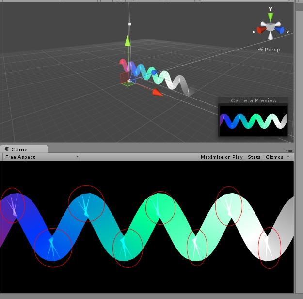
Those little lines can only be fixed by turning off transparency. The mesh is build using quads(?). Those are caused by tiny backwards quads, and partly overlapping quads, inside the same mesh, on sharp bends. Since two faces overlap, transparency double-colors them.
A fix, which is tricky if you already know how, otherwise a huge pain, is to code a hand-built mesh, which "knows" the fan-sections and fixes the ends.
I suspect, as you do, that lineRender and trailRenderer are about the same. Approach #1 sounds horrendous.
Also, probably depends on the equation for these lines (is that really a saw-tooth? Or a sin wave?)
Hello, thank you for your reply. It is a sin wave in the screenshot. I understand now why those dirty little lines appear BUT i really don't know where to turn off transparency. If i set the alpha to 0 then no colors seems to be appearing if is set it to 255(or any other value) then these dirty lines appear. I am comfortable with all of the 3 way but i've tested that approach#1 is so heavy for a mobile and the line sometimes uncontinuous. Is there any 4th way of drawing lines? I've been thinking about it but cannot find any other way atm. And definetely i don't know how to make a custom mesh either :)
Transparency is a shader/material option, if you change to an opaque shader of that material those glitches should go away.
One option you didn't mention, though I doubt it would look as good, and wouldn't plot more than 2 axis: you can draw the curve on a 2dtexture, and apply that to a plane or some 3D object, as a material.
Personally, I would create a custom mesh. The samples on this page showed me how to make my own. http://wiki.unity3d.com/index.php/ProceduralPrimitives
(I would draw a ring of X verticies around each computed point, perpendicular to the direction(slope) of the function at that point. )
I think that the best way of doing it is creating a custom mesh as you mentioned. Looking at the link you shared right now. Thank you!
maybe try this shader: (just ignore the commented zExtrusion :) )
 Shader "TrailWithZWrite" {
     Properties{
         _Color("Main Color", Color) = (1,1,1,0.5)
         _AlphaTex("Base (RGB) Trans (A)", 2D) = "white" {}
         //_ExtrusionAmount("Z Extrusion Amount", Float) = 0
     }
         SubShader{
             Tags{ "Queue" = "Transparent" "IgnoreProjector" = "True" "RenderType" = "Transparent" }
             LOD 100

             ZWrite On
             ZTest Less
             Blend SrcAlpha One
             //Offset 0, -5000

         Pass{

             CGPROGRAM
             #pragma vertex vert
             #pragma fragment frag

             #include "UnityCG.cginc"

             fixed4 _Color;
             sampler2D _AlphaTex;
             //float _ExtrusionAmount;
             float4 _AlphaTex_ST;

             struct v2f {
                 float4 pos : SV_POSITION;
                 half4 color : COLOR0;
                 float2 uv : TEXCOORD0;
             };

             v2f vert(appdata_full v)
             {
                 v2f o;

                 //float3 camDirObjSpace = normalize(ObjSpaceViewDir(v.vertex));
                 //v.vertex.xyz += _ExtrusionAmount * camDirObjSpace;
                 o.color = v.color;

                 o.pos = mul(UNITY_MATRIX_MVP, v.vertex);
                 o.uv = TRANSFORM_TEX(v.texcoord, _AlphaTex);
                 return o;
             }

             fixed4 frag(v2f i) : SV_Target
             {
                 fixed4 texcol = tex2D(_AlphaTex, i.uv) * i.color;
                 return texcol * _Color;
             }
             ENDCG
         }
     }
     FallBack "Unlit/Transparent Cutout"
 }
