Wayback Machinekoobas.hobune.stream
May JUN Jul
Previous capture 13 Next capture
2021 2022 2023
1 capture
13 Jun 22 - 13 Jun 22
sparklines
Close Help
  • Products
  • Solutions
  • Made with Unity
  • Learning
  • Support & Services
  • Community
  • Asset Store
  • Get Unity

UNITY ACCOUNT

You need a Unity Account to shop in the Online and Asset Stores, participate in the Unity Community and manage your license portfolio. Login Create account
  • Blog
  • Forums
  • Answers
  • Evangelists
  • User Groups
  • Beta Program
  • Advisory Panel

Navigation

  • Home
  • Products
  • Solutions
  • Made with Unity
  • Learning
  • Support & Services
  • Community
    • Blog
    • Forums
    • Answers
    • Evangelists
    • User Groups
    • Beta Program
    • Advisory Panel

Unity account

You need a Unity Account to shop in the Online and Asset Stores, participate in the Unity Community and manage your license portfolio. Login Create account

Language

  • Chinese
  • Spanish
  • Japanese
  • Korean
  • Portuguese
  • Ask a question
  • Spaces
    • Default
    • Help Room
    • META
    • Moderators
    • Topics
    • Questions
    • Users
    • Badges
  • Home /
avatar image
1
Question by Jazzer008 · May 16, 2013 at 02:27 PM · meshplaneuvgenerationarbitrary

How to assign UV coordinates to arbitrary mesh.

I have a wall that is randomly generated. Wall

And I need to assign a UV to it. I need any texture I apply to have a constant tile across the wall. Am I going to have to work out magnitudes between vertexes? What's the easiest way to accomplish this?

Comment
Add comment · Show 2
10 |3000 characters needed characters left characters exceeded
▼
  • Viewable by all users
  • Viewable by moderators
  • Viewable by moderators and the original poster
  • Advanced visibility
Viewable by all users
avatar image Owen-Reynolds · May 16, 2013 at 04:12 PM 0
Share

"work out magnitudes between vertexes": Yes.

An easy version takes maybe two lines of code. Just copy XZ distance-so-far directly into V (UV's will gladly go past 1, tiling.) Later, multiply by a scale-factor.

avatar image Fattie · May 16, 2013 at 08:23 PM 0
Share

"Am I going to have to work out magnitudes between vertexes"

Yes. You are going to have to work out everything.

1 Reply

· Add your reply
  • Sort: 
avatar image
2
Best Answer

Answer by aldonaletto · May 16, 2013 at 03:50 PM

If you just want to have a constant 1:1 aspect along each segment, things are easier. If you have to ensure continuity from one segment to the next, then you must also set the uv offset and keep track of the current position when generating new segments.

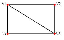
Supposing that you have just calculated the four vertex of a new segment in variables v1 to v4, where v1 is the top-left vertex, v2 is top-right, v3 is bottom-right and v4 is bottom-left, their corresponding uv coordinates can be calculated in variables uv1 to uv4 as follows:

alt text

   ...
   var segW = Vector3.Distance(v1, v2); // calculate segment width
   var segH = Vector3.Distance(v1, v4); // calculate segment height
   var rightX: float = segW/segH; // calculate right X coordinate
   uv1 = Vector2(0,1); // uv relative to the top-left vertex
   uv2 = Vector2(rightX,1); // uv relative to the top-right vertex
   uv3 = Vector2(rightX,0); // uv relative to the bottom-right vertex
   uv4 = Vector2(0,0); // uv relative to the bottom-left vertex
   ...

If you need continuity, then a curX member variable must be kept and updated after generating each new segment:

 var curX: float = 0; // define curX outside any function

   ...
   var segW = Vector3.Distance(v1, v2); // calculate segment width
   var segH = Vector3.Distance(v1, v4); // calculate segment height
   var rightX: float = curX + segW/segH; // calculate right X coord
   uv1 = Vector2(curX,1); // uv relative to the top-left vertex
   uv2 = Vector2(rightX,1); // uv relative to the top-right vertex
   uv3 = Vector2(rightX,0); // uv relative to the bottom-right vertex
   uv4 = Vector2(curX, 0); // uv relative to the bottom-left vertex
   // update curX to the next wall segment. Use only the fractionary
   // part, since big uv values may cause visible artifacts due to
   // the limited precision used in shaders
   curX = rightX % 1;
   ...


wallsegment.png (1.5 kB)
Comment
Add comment · Show 3 · Share
10 |3000 characters needed characters left characters exceeded
▼
  • Viewable by all users
  • Viewable by moderators
  • Viewable by moderators and the original poster
  • Advanced visibility
Viewable by all users
avatar image Fattie · May 16, 2013 at 08:29 PM 0
Share

"and keep track of the current position when generating new segments"

Hey Aldo wot up. Just for the record: i've often found it better in practice to do it statelessly, each "piece of wall" (or whatever) just goes back to whatever the starting point is and figures out for itself, there and then, what it should be.

so, in practice there might be a line of code: "my left hand start = add up lengths of all pieces left of me"

it's extremely simple. very likely they're in a list or something ...... so it's absolutely trivial.

avatar image Fattie · May 16, 2013 at 08:30 PM 0
Share

"Use only the fractionary
// part...
curX = rightX % 1;
" Don't forget if a segment is longer than the texture it needs to be more than 1 delta

avatar image aldonaletto · May 16, 2013 at 09:12 PM 0
Share

Good point: I assumed here that the wall segments are generated sequentially, thus accumulating the segment widths should work as a current left coordinate. If segments aren't generated sequentially, this will fail miserably!

And yes, the right X may be greater than 1.0: that's why the module is applied only when updating curX, which is the next left coordinate. This way, for each segment the left X is in the range 0..1, while the right X may extend to any value; when calculating the left X for the next segment, only the frac part is taken into account.

Your answer

Hint: You can notify a user about this post by typing @username

Up to 2 attachments (including images) can be used with a maximum of 524.3 kB each and 1.0 MB total.

Follow this Question

Answers Answers and Comments

16 People are following this question.

avatar image avatar image avatar image avatar image avatar image avatar image avatar image avatar image avatar image avatar image avatar image avatar image avatar image avatar image avatar image avatar image

Related Questions

How to set up UV for lightmaps for generated meshes? 4 Answers

Mesh.uv is out of range 1 Answer

Mesh building changes in Unity 3.5.6 0 Answers

stretched UV map in generated mesh 0 Answers

Don't we love roads? 0 Answers


Enterprise
Social Q&A

Social
Subscribe on YouTube social-youtube Follow on LinkedIn social-linkedin Follow on Twitter social-twitter Follow on Facebook social-facebook Follow on Instagram social-instagram

Footer

  • Purchase
    • Products
    • Subscription
    • Asset Store
    • Unity Gear
    • Resellers
  • Education
    • Students
    • Educators
    • Certification
    • Learn
    • Center of Excellence
  • Download
    • Unity
    • Beta Program
  • Unity Labs
    • Labs
    • Publications
  • Resources
    • Learn platform
    • Community
    • Documentation
    • Unity QA
    • FAQ
    • Services Status
    • Connect
  • About Unity
    • About Us
    • Blog
    • Events
    • Careers
    • Contact
    • Press
    • Partners
    • Affiliates
    • Security
Copyright © 2020 Unity Technologies
  • Legal
  • Privacy Policy
  • Cookies
  • Do Not Sell My Personal Information
  • Cookies Settings
"Unity", Unity logos, and other Unity trademarks are trademarks or registered trademarks of Unity Technologies or its affiliates in the U.S. and elsewhere (more info here). Other names or brands are trademarks of their respective owners.
  • Anonymous
  • Sign in
  • Create
  • Ask a question
  • Spaces
  • Default
  • Help Room
  • META
  • Moderators
  • Explore
  • Topics
  • Questions
  • Users
  • Badges