Orientation along spline path / Mesh extrusion along path, problem with smooth orientation
Hello fellow Unity coders,
trying to follow a spline path (to extrude a mesh along it later on), I am having a issue which has caused me some headache for a while now: I am using a base mesh segment which is rotated to match the path tangent/derivate. The base segments' default normal orientation is upwards. While walking the path, the segment is rotated to match the spline tangent. This works fine, but when the tangent is pointing down / the segment is oriented downwards, this introduces orientation spinning on the Y axis when traversing the path further downwards, due to the quaternion rotation trying to find the best/shortest rotation axis.
The code used is very simple:
for (int segmentNo = 0; segmentNo < segmentCount; segmentNo++)
{
    t = segmentNo * step;
    arrowHandles[segmentNo].transform.position = splineCatlike.GetPoint(t);
    arrowHandles[segmentNo].transform.up = splineCatlike.GetDirection(t);
}
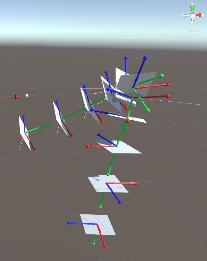
This picture illustrates the problem. The grey quads are test segments, which should be replaced by a mesh in the future. The pink arrow is the quaternion axis on which is rotated. The red, blue, green arrows are showing the quad orientation (EditorHandle-alike, better shown in the second picture). 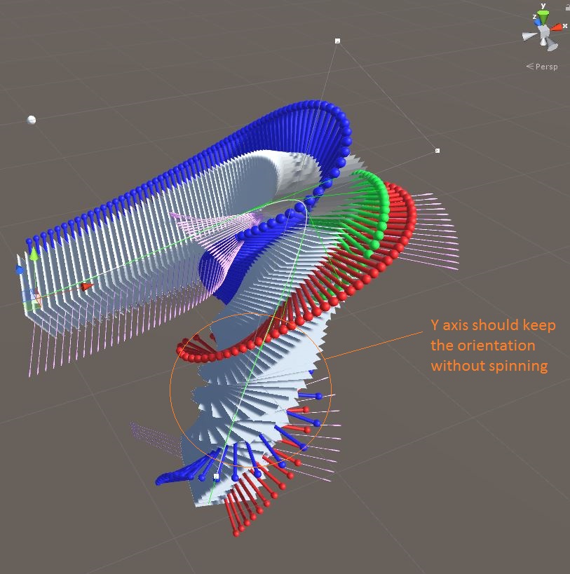
I am trying to keep the code for the segment rotation calculation independent / atomic (not relying on previous segment calculations), to allow the the segment calculation to carried out in random order.
I tried several approaches, some were ok, but all come with downsides (as I am still quite new to this):
Ditching quaternion rotation and lerping along fixed forwards for forward, right, up path orientation. This gives a very stable orientation, but has ugly transitions along path curves / turns. If the transitions would be smoother, this would be fine.
Using quaternions, but fixing the segment.forward on a world.forward (and lerping between both) fails, as the downward quaternion can have different forward orientations, depending on how the path was oriented before going into the downward slope.
Maybe sampling the forward of the path part which is downward pointing, and keeping the segment forward aligned to the averaged forward would work. But this does not sound like clean code.
Thanks for your help, Bamfax
I figure that orientation along a spline path does not come by itself, or by just relying on the quaternion rotation (to align the forward with the curve tangent), and it magically figures out were the normal should be.
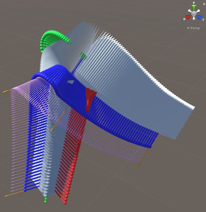
I added now normals to the control points and lerp on the curve legs between them. This works better. See the following picture: Orange arrows are control point normals, pink arrows are lerped in between.

It also shows that the curve/spline/path needs to be thought of like a airplane path, where rolling/banking occurs where the path is bending. This also means that there needs to be some continuity, as the banking on a certain position depends on the previous position.
This makes it more difficult to calculate a single bone / base segment independently from others. $$anonymous$$y intention was to have the base segment calc being atomic / independent, so they can be done in no special sequence.
So this will involve some more thinking, how the orientation along the tangent could be calculated.
I finally found solution this fits this case. The idea here was:
First, to have an automatic orientation along the Y axis. The logic should come up with a decent orientation, no user input required (e.g. user laying out a racetrack manually). It does not need to be pretty, it just shouldn't be superugly.
Second, to allow calculation of the interpolated base segments without a specific order, not having to care about continuity along the path.
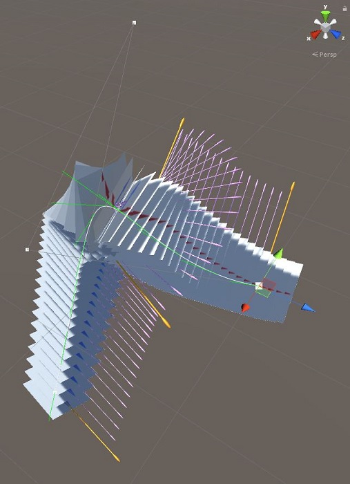
Here is how it looks now. The rotation spinning along the Y axis when the path is going downwards is gone:
The solution is based on the assumption that every path is curvy, and if it's not, we can just fill up with the previous, next or a default normal (ok, some continuity in here - but ok, since its only done for four control points). This assumption allows to understand a control point introducing a curve as sweeping a plane(triangle) with that curve. On that plane we can put a normal on (simple vector cross). This cross also has the max flip on the Y axis from control point to control point limited to 180 degrees. That can probably be handled as an edge case, or with throwing lots of interpolated segments at it.
In the above picture the algo just chooses the triangle plane edge points in the middle of each spline leg.
It could probably be a lot nicer by introducing normal sampling depending on the curve radius. And the normal could probably also serve as basis for calculation a nice airplane flight path with accurate yaw. If someone has good ideas for accomplishing that, I'd be happy to hear from you.
[2]: /storage/temp/97939-splineorientationlerplegs.jpg
