- Home /
UV Mapping for 2D Meshes with 3 Vertices Only
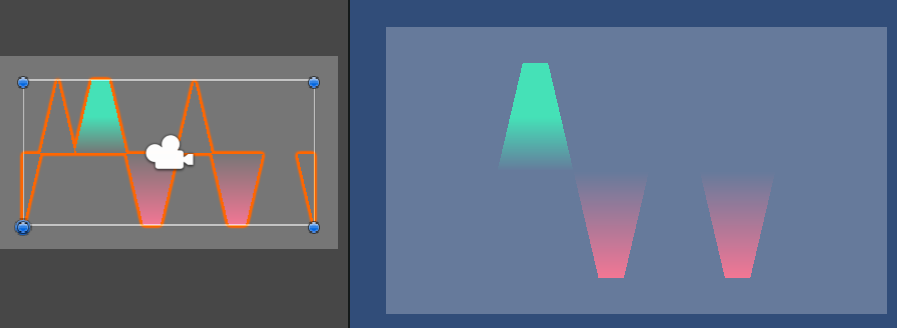
Hello! I'm creating an area graph with multiple 2d meshes. I'm trying to add a material with a gradient to each 2d mesh using uvs. It works for meshes with 4 or more points, but meshes with only 3 vertices are invisible. How can I fix this problem? 
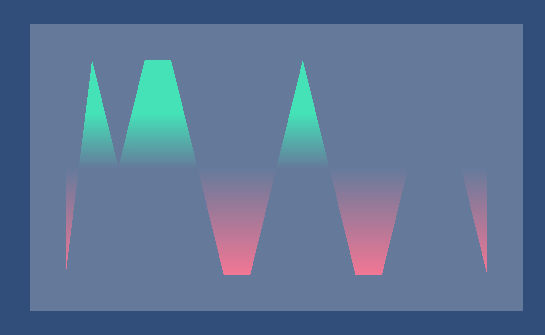
As you can see, all the meshes are drawn. However, the ones with only 3 points are not colored. The uvs for the first triangle (that doesn't work) are (0,1), (0,0), and (1,1). The uvs for the third triangle (that does work) is (1,0), (0.66,1), (0.33,1), and (0,0). This is my first time posting, so if there is any information you need, let me know. Any help would be appreciated!
It's a bit tough to tell for certain based on your description as-is. Specifically, you list 3 vertices for your "first triangle" and 4 vertices for your "third triangle", which distinctly doesn't describe a triangle.
It sounds like a winding-order (i.e. clockwise/counter-clockwise vertex order) issue with the Meshes themselves most likely, but it's hard to tell without knowing vertex positions and triangle ordering specifically.
The meshes are triangulated using ear-clipping and the points are counter-clockwise, at least I think they are lol. And sorry about that I meant the third mesh. There's no such thing as a triangle with 4 points.
Here are the points and uvs of the first two meshes, which don't work and have 3 points each. 
Here are the points and uvs of the third. This has 4 points and is visible. 
Well, with a quick test, I can already tell you that you'd want clockwise winding order on the vertices (or a double-sided shader that doesn't cull back faces). Based on punching in the numbers myself (but having no idea what your triangle ordering is like, so intentionally having non-matching shape results on the trapezoid shape), I'm fairly confident that this is the problem you're facing.
Answer by Bunny83 · Nov 05, 2021 at 01:33 AM
The meshes are triangulated using ear-clipping and the points are counter-clockwise, at least I think they are lol.
Well, first of all in Unity which uses a left handed system the winding order should be clockwise, not counter clockwise. Since you only "think" they are winding in a certain direction, I think you should clear that up because they may face into the wrong direction. However you can immediately check this by switching the camera into 3d mode and move it to the other side. If you see those missing triangles there, they have the wrong winding order. Though if you create those triangle from code, it should be quite easy to reason about the winding order when you pay attention.
Your screenshots of your vertices are not helpful at all since they are useless without the triangle definition. Also your meshes appear to be 2d meshes, why do your coordinates vary in all 3 axis? If they don't it's not really clear what those 3 values represent if it's not x, y and z.
It's also not clear how the texture actually looks like. Maybe you mapped an empty region? If you need further help with this, you should edit your question and add more details. Preferable the relevant code that generates the mesh or at least the exact vertex, uv and triangle data as text, not as an image.
Thank you! It turns out the triangle ordering was counter-clockwise for meshes with only 3 vertices. (I didn't write the ear-clipping algorithm, so I don't know why that is.) Meshes with 4 or more points were ordered clockwise, which explains why the rest showed. All I did to fix this problem was reverse the list containing triangle ordering when there are exactly 3 vertices, turning counter-clockwise to clockwise.
Your answer

Follow this Question
Related Questions
can't put texture materials on imported mesh. 1 Answer
UV tiling to fill face? 1 Answer
Split a mesh while using same UVs and texture position. 0 Answers
Assigning UV Map to model at runtime 0 Answers
Apply texture to a mesh on all 3 sides 2 Answers
