Set view frustum shape
I want to set the shape of the view frustum so that the height of the near clipping plane is the same height of the far plane. The effect I'm looking for is sort of a combination of Orthographic and Perspective projection where you can see the left/right of a 3D object but not the top/bottom.
Is this possible?
Example Images:
Here is what I think the result may look like, if a cube is places on the left of the screen, you can see the right side of it (Green), on the right you see the left side (red). But, you never see the top or bottom of the cubes.

Here is my understanding of the 2 major view frustums in Elevation, Plan and End View. The Far CLipping plane in black, the near clipping plane in red. The 3rd Frustum is what I am looking for, with the Near Clipping Plane the same height as the Far.

Because I want to see the sides of objects as I scroll around. It's just for a prototype for now, trying to pin down the major points so the artist has some direction.
Could you please sketch this for an example object (cube?) and show us what you want it to look like as seen through the camera? Because I think nobody understood what exactly you are trying to do.
Prepare your bowels for awful programmer art :p
EDIT: OP updated. Did I make things better or worse?
It is possible, from what I understand, but you need to alter the camera's projection matrix. See this question (http://answers.unity3d.com/questions/381502/making-a-camera-semi-orthographic.html) for more details; I don't really know anything about matrices.
Sorry, but what you are trying to do is impossible. However, it is difficult to explain why.
Let me try anyway:
as you can already see in your image, your y-Axis is not truly orthographic. If it were, the back vertical edges of your cube would have to be the same height as the front vertical edges. They are not, they are perspectively distorted (=fewer pixels).
orthographic projections don't have vanishing points. Parallel lines are always parallel, no matter which direction they're facing
perspective projections always have exactly one single vanishing point for every set (=direction) of parallel lines
what you would need is one vanishing point for every "row" of objects (=horizontally grouped cubes in your example), which would be something like a vertical "vanishing line". That is not possible, since any specific x/y coordinate in the front would map to an infinite number of y coordinates in the back (see image)
or somewhat more mathematical: perspective projection does not distort "left" or "right", nor "top" or "bottom", it distorts depth (=front and back). for this, it uses homogeneous coordinates. But these influence all axes. It either scales by (the inverse of) depth, or it doesn't. You simply can't have both.
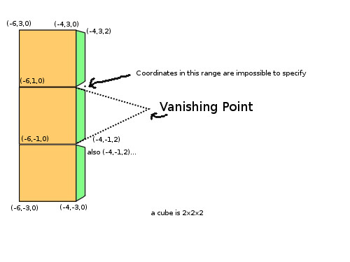
Look at the image below: Assuming "standard" coordinate axes +X=right, +Y=up, +Z=depth, the top left corner of the bottom cube has the same coordinates as the bottom left corner of the cube above it, in this case (-6,-1,0). If the cubes are 2x2x2, the bottom left corner is therefore (-6,-3,0), bottom right (-4,-3,0), and top right (-4,-1,0). Now, if you go into the depth for the back face of that cube, look at its top right corner: it it is located at Z+2, and becomes (-4,-1,2). But the bottom right corner of the center cube also has the coordinates (-4,-1,2). But they are at different pixel positions! Furthermore, the area between these two "identical" points cannot be reached by any valid cartesion coordinates.
What kind of workarounds are available?
Well, this highly depends on what you want to do.
In theory, you would have to render each object using its own off-axis projection matrix. AFAIK, this is not possible in Unity. I tried some experiments once using OnRenderObject, Graphics.DrawMeshNow, etc., but it seems you can't modify the projection matrix during rendering, it would create undefined areas that can never be filled (again, see image). Also, you couldn't "share" the depth buffer between these sections, for the same reason.
If you "only" have a grid of vertical rows and don't intend to move objects smoothly between them, or even interact, then you could split your screen into several individual cameras, each one rendering one particular row. You wouldn't even need adapted projection matrices in this case.
A more flexible method would be to first render each object into a rendered texture (using an off-axis projection matrix with an x-shear depending on where you want to place that rendered texture on your screen), which you can then arbitrarily shift along y, without changing its perspective, hence simulating an "orthographic view" along that axis. But you would lose 3D (=depth) information of your objects, and therefore occlusion, and so on.
But there is no "clean" solution, or even a single 4x4 matrix which can accomplish that.
You are partially right ;) Yes, it won't look like in the picture he posted above. In the projection he wants lines along the z axis will always be parallel to the x axis. If he really wants the lines to be diagonal, it's an impossible projection.
However if you take a look at his viewing frustum, that should be possible, but it won't produce the image seen above ;)
I actually wanted to point that out when i posted my partial answer, but had no time. I will try to setup an example to test it out ;)
I saw that my projection was wrong just before I posted it up so it won't look exactly like my picture. But I am also lazy :p
This method has been abandoned by the designer for high quality sprites anyway, but it is still an interesting topic I feel.
Could be interesting if you needed something like a hallucination scene in a 2.5D platformer.
I can't seem to upvote your answers, I would if I could ;)
Hm, I'm still not convinced it's possible with standard homogeneous coordinates. Perspective projection "misuses" w to scale x and y by 1/z. For the hybrid approach, you woud need to compose x' from something like x/z, while leaving y unmodified by z, which I don't think is possible.
But I fear my transformation matrix skills are too far in the past to be certain, so I'll wait for your hopefully successful example ;-)
The other question, of course, is whether this hybrid approach really brings you any real benefit at all, since you would essentially loose all depth cues and depth information, so your eyes/brain will have a hard time distinguishing any "side" wall from the "front" walls. But again, that depends on the application and what it is intended to do, I guess.
If the intention is to use sprites, on the other hand (in the sense of a pre-rendered object that still reacts to horizontal shifts), then there would be no need to mess with the camera's projection matrix at all. Ins$$anonymous$$d of the standard N x 1 sprite map where each step depicts the object at another Y-rotation, you would need to extend that to a N x $$anonymous$$ 2D-map, where you use an off-axis projection matrix with different X-shifts for each row, and then choose a row depending on the actual screen-X of your sprite's location. This would have the additional advantage that you could include depth perspective into your sprites, which would come a lot closer to the picture I posted.
If the sprite map is already 2D because the object is animated - well, have fun creating your new 3D sprite map... ;-)
Unfortunately you're right ;) It's because the z-divide always affects the whole matrix / vector result as it's implemented in the w coordinate. That's actually the only way to "divide" by the z coordinate. I try to explain that in my answer.
Anyways your answer is the correct one ;)
You just have to build your own projection matrix like Loius said. I don't remember the exact format of Unity's projection matrix, but i can give it a try. I have no time at the moment, maybe later, stay tuned (or do some research yourself ;))
edit:
Wolfram is right.
In a matrix you can only perform multiplications and additions / subtractions on single input values. The perspective projection requires you to divide the incoming x and y coordinates by the incoming z coordinate. Since you can only multiply and add up the results for each component that's not possible.
However there is a way. The 4th "w" coordinate. When you transform a vector with a matrix the endresult will be divided by the resulting w-component. Here it's possible to bring the z value in, but the problem is it will always affect the whole vector. It can't be done for a single component.
What you need would be to just divide the x coordinate but calculate y in a different way. That's not possible.
Here's an example:
       input vector
    Xin  Yin  Zin  Win
     \/   \/   \/   \/
     |    |    |    |
     |    |    |    |
     Sx+  0 +  0 +  0  =  Xout
     |    |    |    |
     0 +  Sy+  0 +  0  =  Yout
     |    |    |    |
     0 +  0 +  0 +  0  =  Zout
     |    |    |    |
     0 +  0 + -1 +  0  =  Wout

 At the end the out vector is "normalized" by dividing the vector by Wout.
 Wout will be -Zin and gives the desired perspective effect, but on all axes.
Btw Sx and Sy are scaling factors which are calculated from the cameras FOV and the screens aspect ratio.
Note that this is just a simplification and doesn't produce z values for the depthbuffer. Usually you also have values at 3rd row, 3rd and 4th column. Something like that:
edit
However, i guess in a custom shader you could realise that behaviour ;) You can do a lot more complex things in a shader ;)
[1]: http://msdn.microsoft.com/en-us/library/windows/desktop/ee418867%28v=vs.85%29.aspx
$$anonymous$$inda looks like I have to set the t and b values to be the height of the far plane. However the hells I do that.
