Tiling UV mapping?
My screenshot describes my question clearly (better than words I think)
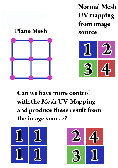
So, is it possible to have more control with the UV mapping and decide which portion of the texture to map on the Mesh (in a tiling style).
At this point are you familiar with the uv array? http://docs.unity3d.com/Documentation/ScriptReference/Mesh-uv.html
which is just part of Mesh http://docs.unity3d.com/Documentation/ScriptReference/Mesh.html
Based on what you have described: Just play with uv values of 0.0, 0.5 and 1.0.
You'll soon get the idea! Your image just goes from 0 to 1 in each direction, it's that simple. Your quadrants are just the obvious. DRAW A DIAGRAM of your eight triangles and start setting the uvs. Enjoy!
if you get big into vertices consider this fount of interesting information and downloads, etc etc http://answers.unity3d.com/questions/193695/in-unity-is-there-a-fast-way-to-find-nearby-triang.html
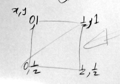
Now here's a diagram:
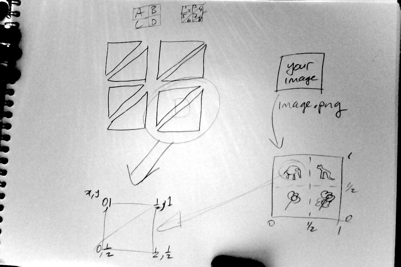
large image: CLICK HERE TO SEE DIAGRAM PROPERLY
So, say you want your ELEPHANT to appear in area D. The elephant obviously enough exists at the coords I have written here...
Your area D is two triangles (7 and 8). So .......... there are six verts (two triangles ... 2x3 = 6 !!) Just set the six verts to those values!! 0,,5 etc. It's that simple !!!
OF COURSE as Owen points out, this "hello mesh" exercise only works if everything is completely regularly-spaced and so on. Enjoy!
Helpful notes
If you're learning to make procedural mesh ... why bother? There's always an easier way! :)
When you're making procedural mesh, DO NOT BOTHER trying to make "shared" vertices in the vertices array.
When making procedural mesh, it is (typically) poor practice to bother trying to share the verts in the vert array.
Don't forget to play with the normals too! Try adding a torque to the normals and precessing them!!
If, ignoring point 1, you decide to get in to making mesh. It is utterly critical to remember. When it comes to doing the actual weave, YOU MUST DRAW A DIAGRAM. Please do not ignore this point for your own sanity!
Read point 5 over and over.
Don't forget thee tris are CLOCKWISE in unity. I think.
It is critical that one fully internalises the following......
http://answers.unity3d.com/questions/266972/detecting-mesh-orientation.html (thank God for Whydoidoit)
it is critical one understands the common misunderstanding even sophisticated people make, which is explained in extravagant length here
http://answers.unity3d.com/questions/193695/in-unity-is-there-a-fast-way-to-find-nearby-triang.html
Triple-check - have you addressed point 6?
Also address point 5 !!
The hitchhiker's guide suggests that anyone who weaves mesh prefers a Canson "Croquis" 90g/m2 sketch block (the one with the orange cover) for drawing diagrams - I have one of the rare A3s just now, it's great. Of course, you could use any sketchpad, but you know what Einstein said. Enjoy!
Thaks to Fattie for the excellent explanation. Just want to add - regarding the pt.2 of Helpful Notes:
Each of the mesh polygons needs to have its own, not shared, set of vertices. Like the cube primitive checked with mesh.vertices.Length - returns 24 - which simply is 6 polygons x 4 vertices each.
(I was also tending to make it wrong and this checkout helped me to confirm the right understanding.)
Doesn't changing it to have it's own vertices break smooth shading though? In this case, it's just a plane, but in a object with more dimensionality, changing the shared vertices out will break smooth normals.
Thanks for a great answer! A sub-question... it seems that you're saying tiling cannot be achieved within a single face - that each "instance" of the image is a separate UV map onto its own face, is that correct? But then how, for example, does a texture become tiled onto a large plane, like when you create a simple "ground" plane in Unity and map a "sand" texture onto it - isn't that tiling over a single face?
try coords like 0 to "20" rather than 0 to "1" !
"within a single face..." there's no "faces" in mesh .. just triangles. try just setting up one triangle, and experimenting with assigning all sorts of values to the uv! have fun
Could you explain the reasoning behind points 2 and 3?
It would probably be easier to just use 4 planes, then 4 materials (one for each numeral,) which you swap in and out. Other approaches might squeeze out a little more speed, but I not much and you probably won't need it.
Moving around UVs can easily stretch your texture, flip it, repeat ... . But to have a "non-continuous" texture, like the four 1's, all of the interior verts would need to have been previously split in the modelling program. That's just a basic concept in unwrapping.
If you did that then you could code using mesh to hand-set all 16 UV coords, but a giant pain looking up that the middle-right vert is stored in slot #7, etc... .
You could also write a custom shader, which would work for a 4-vert plane. For example, if(uv.x>0.5 && uv.y<0.5) uv.x-=0.5; would shift the 3 into the 4 slot(?). But there are 256 combinations, and might take several very mathy shades to cover them all.
To elaborate, the hard part of setting the UVs in code is you have to know how the verts were numbered during the export. It's possible the verts making the lower-left square are numbered 0,1,4 and 5; or 3,7,6 and 4; or anything else.
The verts for the other 4 squares may not follow the same pattern, so you can't just reuse code with "vertNum+4".
To find the numbers, you can print out the vert coords in Unity. Lots of verts have duplicate coords, so you have to guess which is part of which square.
But, sure, once you get a 0-15 picture of how the plane verts are numbered, then you just need four lines that look like uv[3]=new float2(0,0.5f); setting uv's for whichever corner of the texture you want.
hmm .. export ... ?
it's only 8 triangles, you just make 'em ! you know Owen, I believe he only meant it as a "hello $$anonymous$$esh" learning example
all of what you say is true of course. unfortunately it appears to be the case of a disappearing new user, so another hour wasted
So, I decided to make the mesh of my plane a bit simpler and made it only one cell rather than four cells.
It seems to work great, only the numeral '2' tile of my image appears on my plane when I play-test Unity.

So, if I come back to my previous four-cells plane example, it would be impossible to have the same results without adding more vertices (splitting) as Owen instructed?
The problem is the 5 inner vertices which are shared by two or four quads. You can only specify one texture coordinate per vertex, so it's not possible to set all four corners of all four tiles to different values.
You have to split the vertices, so each tile have it's own 4 vertices. That means your 2x2 quad mesh which has 9 vertices would need 16 vertices. When you create the mesh procedurally, it's even much easier. Always four vertices in the array will make up one quad. The triangle array will contain blocks of 6 values which always refer to one four-vertices-block.
I can post an example if you really want, but those two answers should be enough ;)
not that I'm aware of. For example, the Unity native cube is made of 24 verts, not 8 as it would at first seem. You have more flexibility with manipulating vert UVs, colours and tangents.
No ;) You have 2 triangles per quad. One triangle needs 3 indices so one quad needs 6 indices. When you have 4 quads (2x2) you would need 4x4 vertices and 4x6 indices. So you need 16 vertices and 24 indices.
If it makes things easier, you can safely think of quads/squares ins$$anonymous$$d of triangles -- 4 verts/quad, total of 16, is just fine. The only time tris come into play is when making the tri array. "Quad" 4,5,9,10 becomes two tris 4,5,9 and 9,10,4 (which is an easy pattern.)
Don't get too hung up on "everything is really tris." Everything is also in binary, but the computer just handles it. Graphics cards gladly take quads as input (a tri-list is the last resort out of 5 ways to list faces, but easy to understand.) The modellers I know prefer to use quads whenever they can.
Also, suggest: vertices[0]=new Vector3(-1,1,0); ins$$anonymous$$d of three lines.
