- Home /
How to differentiate between similarly coloured faces
Hello everyone!
I make simple VR presentations and I'm struggeling to make the difference clear between similarly coloured faces. A good example is this piece of stairs:
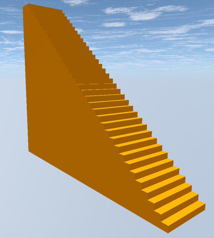
Especially when trying to climb the stairs this becomes visually confusing.
We try to avoid placing textures on these objects, instead using simple colours.
Is it somehow possible to blacken the edges, just as is standard in CAD software? Example: 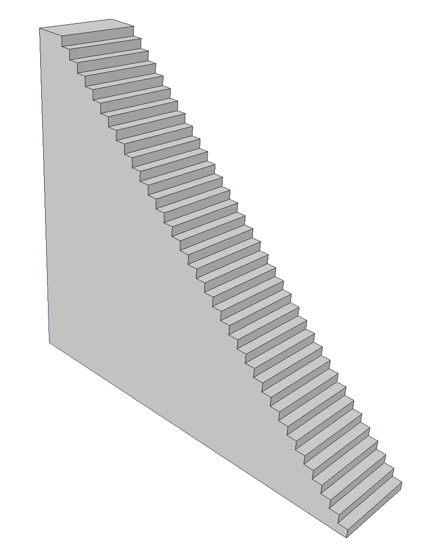 Thanks in advance everyone! -Laurence
If the starts always have those 90 degree drops, you could just use a directional light to make the tops brighter. It'd never strike the other parts of the staircase due to geometry etc.
Answer by dan_wipf · Nov 30, 2018 at 07:37 PM
why don’t you select the tops of the stairs, and make them diffrent material? i don’t know much about cad, but in blender you can select the vertecies you want and add them to a new material
EDIT: Shader and Pictures
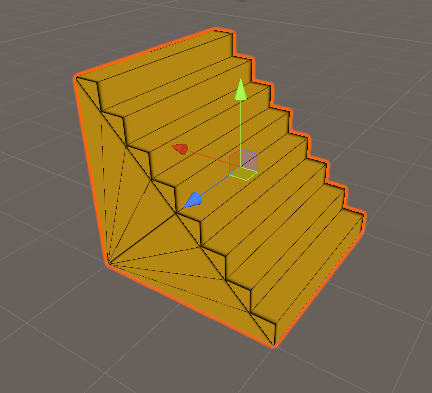
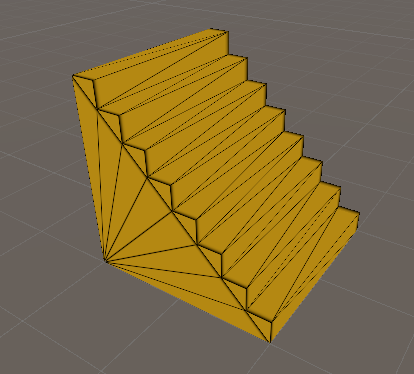
Above you see my implemention of a Quadbased Wireframe Shader and a Triangle Wireframe shader
The Code is this:
 Shader "GeometryShading/Wireframe"
 {
     Properties
     {
         [HideInInspector]_MainTex("MainTex", 2D) = "black" {}
         _WireSmoothness("Wireframe Smoothness", RANGE(0, 400)) = 400
         _WireThickness("Wireframe Thickness", RANGE(0, 10)) = 10
         _WireColor("Wireframe Color", color) = (1,1,1,1)
         _Color("Main Color", Color) = (1,1,1,1)
         [Toggle] _RemoveDiag("Remove diagonals?", Float) = 0.
     }
         SubShader
         {
             Tags{ "Queue" = "Geometry" "RenderType" = "Opaque" }

             //Simple Color Base Shader

             Pass
             {

             CGPROGRAM
             #pragma vertex vert
             #pragma fragment frag
             #include "UnityCG.cginc"


             float4 _Color;

             struct v2f
             {
                 half3 worldNormal : TEXCOORD0;
                 float4 pos : SV_POSITION;
             };

             v2f vert(float4 vertex : POSITION, float3 normal : NORMAL)
             {
                 v2f o;
                 o.pos = UnityObjectToClipPos(vertex);
                 o.worldNormal = UnityObjectToWorldNormal(normal);
                 return o;
             }

             fixed4 frag(v2f i) : SV_Target
             {
                 fixed4 c = 0;
                 c.rgb = _Color;
                 return c;
             }
             ENDCG
         }


         //Wireframed Shader with Option to disable Diagonals
             Pass
             {
             Cull Back
             CGPROGRAM
             #pragma vertex vert
             #pragma fragment frag
             #pragma geometry geom
             #pragma shader_feature __ _REMOVEDIAG_ON
             #include "UnityCG.cginc"

             float _WireSmoothness;
             fixed4 _WireColor;
             float4 _Color;
             uniform float _WireThickness;
             uniform sampler2D _MainTex; uniform float4 _MainTex_ST;

         struct appdata
         {
             float4 vertex : POSITION;
             float2 texcoord0 : TEXCOORD0;
             UNITY_VERTEX_INPUT_INSTANCE_ID
         };
         struct v2g
         {
             float4 worldPos : SV_POSITION;
             float2 uv0 : TEXCOORD0;
             UNITY_VERTEX_OUTPUT_STEREO
         };

         struct g2f
         {
             float4 pos : SV_POSITION;
             float4 bary : TEXCOORD0;
             UNITY_VERTEX_OUTPUT_STEREO
         };

         v2g vert(appdata v)
         {
             v2g o;
             UNITY_SETUP_INSTANCE_ID(v);
             UNITY_INITIALIZE_VERTEX_OUTPUT_STEREO(o);
             o.worldPos = mul(unity_ObjectToWorld, v.vertex);
             o.uv0 = TRANSFORM_TEX(v.texcoord0, _MainTex);
             return o;
         }

         [maxvertexcount(3)]
         void geom(triangle v2g IN[3], inout TriangleStream<g2f> triStream) {
         float3 param = float3(0., 0., 0.);
         float wireThickness = 13 - _WireThickness;

         #if _REMOVEDIAG_ON
             float EdgeA = length(IN[0].worldPos - IN[1].worldPos);
             float EdgeB = length(IN[1].worldPos - IN[2].worldPos);
             float EdgeC = length(IN[2].worldPos - IN[0].worldPos);

             if (EdgeA > EdgeB && EdgeA > EdgeC)            { param.y = 1.;}
             else if (EdgeB > EdgeC && EdgeB > EdgeA)    { param.x = 1.;}
             else                                        { param.z = 1.;}
         #endif

             g2f o;

             o.pos = mul(UNITY_MATRIX_VP, IN[0].worldPos);
             o.bary.xyz = (float3(1., 0., 0.) + param) * o.pos.w * wireThickness;
             o.bary.w = 1 / o.pos.w;
             UNITY_TRANSFER_VERTEX_OUTPUT_STEREO(i[0], o);
             triStream.Append(o);

             o.pos = mul(UNITY_MATRIX_VP, IN[1].worldPos);
             o.bary.xyz = (float3(0., 0., 1.) + param) * o.pos.w * wireThickness;
             o.bary.w = 1 / o.pos.w;
             UNITY_TRANSFER_VERTEX_OUTPUT_STEREO(i[1], o);
             triStream.Append(o);

             o.pos = mul(UNITY_MATRIX_VP, IN[2].worldPos);
             o.bary.xyz = (float3(0., 1., 0.) + param) * o.pos.w * wireThickness;
             o.bary.w = 1 / o.pos.w;
             UNITY_TRANSFER_VERTEX_OUTPUT_STEREO(i[2], o);
             triStream.Append(o);
         }

         fixed4 frag(g2f i) : SV_Target
         {

             if (!any(bool3(i.bary.x <= 0.5, i.bary.y <= 0.5, i.bary.z <= 0.5)))
             {
                 discard;
             }

             float minDistanceToEdge = min(i.bary[0], min(i.bary[1], i.bary[2])) * i.bary[3];
             float4 basecol = tex2D(_MainTex, i.bary);
             if (minDistanceToEdge > 0.9)
             {
                 return fixed4(basecol.rgb, 0);
             }
             float t = exp2(_WireSmoothness * -1.0 * minDistanceToEdge * minDistanceToEdge);
             fixed4 finalcolor = lerp(_Color, _WireColor, t);
             return finalcolor;
         }

             ENDCG
         }
     }
 }
if you have further questions, just ask
That's not really an option here I'm afraid, the edits have to be done inside Unity itself. Isn't there a way to render the model with it's edges blackened just like in the example?
well there are diffrent approaches. if you want to have all objects with a line on the edges, you can use an image effect, if you want to use it only on a single object, you could use some kind of wiredframe shader. what do you think, will it be in your project?
well in addistion the wiredframe system is mostly for pc, duetue the gemoetey shader technique. and can be outlined as triangles or quads.
This wireframe shader sound interesting, as it would be only a few models that have to show their edges. Can you point me into the direction of this wireframe shader?
Thx,
well, i think, it’s the closest you could get without any image(post rendering) effect. difficult task what you want, but what @TreyH said about light setup could possible work aswell. I just think without any uv unwrap/propper texturing you will not achieve the desired outlines of an object
btw. with a work around you could also get rid of the side lines, of the stair, but i can’t tell you if this would work with your model. (how your cad is calculating the faces, one big face of the side face or multiple quads/triangles)
Thanks, now we're getting somewhere!
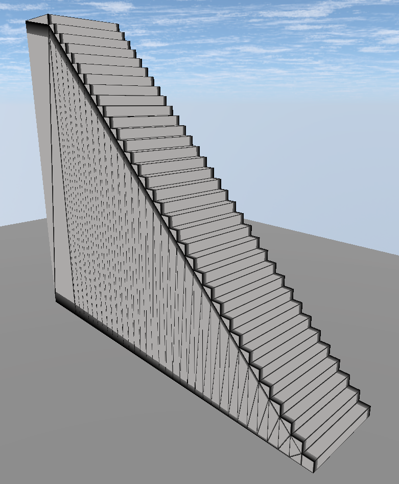 The steps themselves are distinguishable enough, but the sides are indeed a mess. In my CAD software the model is a solid, thus the side is a single face. When converted for use in Unity though the face is split in triangles.
Would there be an elegant workaround, to remove the side lines?
yes indeed there is.
go to the model’s inport settings, on the first tab there is a toggle called keep quads enable it.
this generates a second material slot in the mesh renderer. you should create a second material (standard shader is fine) asign it to the second material slot, in the first slot is your custom wireframe shader material.
now the trick is to sync the materials color.
might want to build an editor window or a script which handle this in inspector, i could post a simple code later, when i’m on a pc
Your answer

Follow this Question
Related Questions
Using RenderTextures in editor script 0 Answers
Sprite animation from 2D to 3D 2 Answers
How can i get my quad to only render my texture without stretching it? 1 Answer
How to add texture to Blender objects properly? 2 Answers
3D models has white parts 0 Answers
