- Home /
Drawing a camera-facing circle like Unity's SphereCollider gizmo
I am trying to emulate the way Unity draws the gizmo for the SphereCollider component.

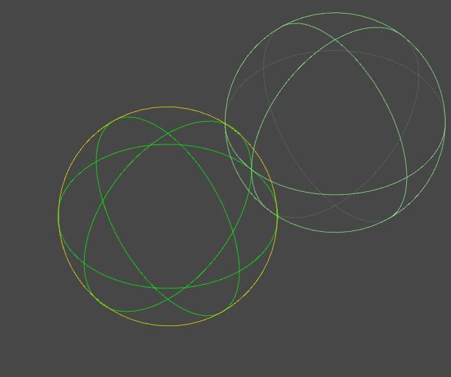
On the right side, the SphereCollider gizmo. This is an orthographic camera view to show an important point: The gizmo is created from three wire discs at the cardinal axes, plus an additional circle with its normal seemingly pointing towards the camera. I've highlighted this camera-view circle in yellow in my own gizmo on the left. So far so good, both look the same. However, in perspective camera view my camera-facing gizmo circle is no longer correct:

We can see that the camera-facing circle in yellow is actually distorted in a way, that doesn't line up with the other discs like the Unity SphereCollider gizmo does.
What do I have to do to adjust for this distortion and make the yellow circle appear as if it were an outline of the imaginary sphere?
Here is some example code of what I'm doing:
 using UnityEditor;
 using UnityEngine;

 public class Sphere : MonoBehaviour
 {
     public float radius = 0.5f;

     [DrawGizmo(GizmoType.Selected | GizmoType.NonSelected, typeof(Sphere))]
     private static void DrawGizmos(Sphere sphere, GizmoType gizmoType)
     {
         // The sphere is defined by its radius and position, rotation and
         // scaling of the attached Transform component.
         Handles.matrix = sphere.transform.localToWorldMatrix;

         // "Cardinal circles"
         Handles.color = Color.green;
         Handles.DrawWireDisc(Vector3.zero, Vector3.right, sphere.radius);
         Handles.DrawWireDisc(Vector3.zero, Vector3.up, sphere.radius);
         Handles.DrawWireDisc(Vector3.zero, Vector3.forward, sphere.radius);

         // Now draw a circle that looks like the outline of the imaginary sphere.
         // My first attempt was to just draw a camera-facing disc, but this
         // doesn't account for perspective distortion like the SphereCollider gizmo does.
         Handles.color = Color.yellow;
         Vector3 toCamera = (Camera.current.transform.position - sphere.transform.position).normalized;
         Handles.DrawWireDisc(Vector3.zero, toCamera, sphere.radius);
     }
 }
When switching to 2D mode, the issue becomes more clear. No matter where my camera is positioned, the yellow circle's normal should point along the z-axis, but since I calculate a vector towards the camera, the circle is rotated slightly when I pan the camera left or right. For a fixed-axis or 2D view I could simply lock the additional circle to the closest cardinal axis, but I would like to fix the problem for the 3D perspective case as well.
Thank you for your help!
Answer by Xarbrough · Mar 17, 2018 at 12:34 AM
I've actually found some reference code in the UnityEditor.Handles class and came up with the following solution, that does what I want. However, I must admit, I don't understand the math behind it at all, but I'd like to, so if anyone can explain what this code does, I'll count that as the answer to my question.
 Handles.matrix = volume.transform.localToWorldMatrix;
 Handles.color = Color.green;
 Vector3 position = Vector3.zero;

 Handles.DrawWireDisc(position, Vector3.right, volume.radius);
 Handles.DrawWireDisc(position, Vector3.up, volume.radius);
 Handles.DrawWireDisc(position, Vector3.forward, volume.radius);

 if (Camera.current.orthographic)
 {
     Vector3 normal = position - Handles.inverseMatrix.MultiplyVector(Camera.current.transform.forward);
     float sqrMagnitude = normal.sqrMagnitude;
     float num0 = volume.radius * volume.radius;
     Handles.DrawWireDisc(position - num0 * normal / sqrMagnitude, normal, volume.radius);
 }
 else
 {
     Vector3 normal = position - Handles.inverseMatrix.MultiplyPoint(Camera.current.transform.position);
     float sqrMagnitude = normal.sqrMagnitude;
     float num0 = volume.radius * volume.radius;
     float num1 = num0 * num0 / sqrMagnitude;
     float num2 = Mathf.Sqrt(num0 - num1);
     Handles.DrawWireDisc(position - num0 * normal / sqrMagnitude, normal, num2);
 }
The original code is from the internal Handle.DoRadiusHandle method, but I also wanted to factor in the Transform scaling, so I experimented until I got it working, without knowing what's behind it.
This was exactly what I was looking for. As far as the math behind it , I am too lazy to work out why it works.
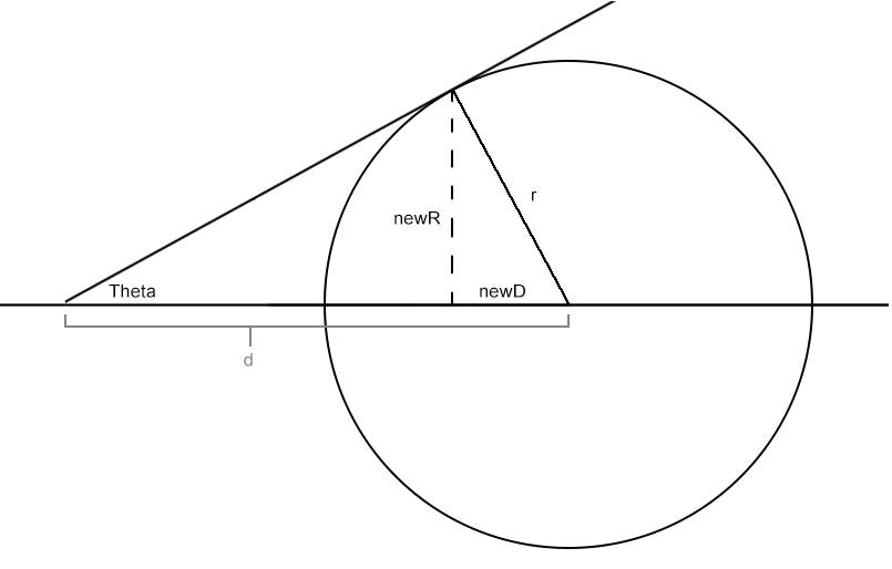
I took the time to understand what's actually happening here. It has to do with this: https://en.wikipedia.org/wiki/Angular_diameter
You can rewrite the formulas to the much simpler (imo) equivalent:
 float r = volume.radius;
 float d = normal.magnitude;
 float theta = Mathf.Asin(r / d);
 float newD = r * Mathf.Sin(theta);
 float newR = r * Mathf.Cos(theta);
 Handles.DrawWireDisc(position - newD * normal.normalized, normal, newR);
Theta represents the apparent angle that the sphere takes up in the view.
newD is how far to shift the circle towards the camera
newR is the new radius of the circle

The new circle will now be positioned to encompass the entire apparent area of the sphere from the camera perspective. You an can visualize this pretty nicely by just passing in a fixed value instead of the camera position, then you can move the camera around to see that a circle is being drawn somewhere on the surface of the sphere, facing the fixed position, but not at the center of the sphere, and thusly with a radius smaller than the sphere radius.
I think what happened with the incomprehensible math is that it was reworked to attempt to avoid the trig functions and square root. The trig functions end up falling out if you combine some terms but then things get a bit ugly.
Your answer

Follow this Question
Related Questions
Multiple Cars not working 1 Answer
Gizmo equivalent of Handles.DrawSolidArc? 0 Answers
Distribute terrain in zones 3 Answers
How to build Gizmos Handles 0 Answers
Editor Gizmo logic question? How do the gizmos move relative to camera 1 Answer
