stitch spheriphied terrain-like (6) planes (removing gaps from edges)
Hello everyone.
My current goal, is a procedurally generated planet. Following the Spore technique, I made a cube out of 6 planes, projected grayscale stencils over them, and used the generated textures, as heightmaps for each face. then, spheriphy everything.
The only problem is, there are huge seams on every face border.
I do not have access to my code at the moment, but I'll provide it as soon as somebody is interested in helping me thinking this out. I'm just curious if there is a missing part (and how to accomplish it) to average vertices on the edges of my 6 faces (and to make them match in height/distance from center) Thank you all, and have a good day.
 var heightMap : Texture2D;
 var superficie:GameObject;
 var calotte:GameObject[];
 var recalculateNormals = false;
 var radius : float = 3;

 var top_tex:Texture2D;
 var top_dif:Texture2D;
 var colore = Color.green;
 var colore2 = Color.yellow;

     function sferizza()
         {

         for (var child : Transform in transform)
         {
                 var baseVertices : Vector3[];
                 var mesh : Mesh = child.GetComponent(MeshFilter).mesh;

                         if (baseVertices == null)
                         baseVertices = mesh.vertices;
                         var vertices = new Vector3[baseVertices.Length];
                         for (var i=0;i<vertices.Length;i++)

                         {
                         var vertex = baseVertices[i];
                         vertex =vertex.normalized * radius;
                         vertices[i] = vertex;
                         }

                         mesh.vertices = vertices;
                         if (recalculateNormals)
                         mesh.RecalculateNormals();
                         mesh.RecalculateBounds();
                         DestroyImmediate(collider);
                         child.gameObject.AddComponent(MeshCollider);
             }
             DestroyImmediate(collider);
             gameObject.AddComponent(MeshCollider);
         }

         function duplica()
         {
         for (var orientamento = 0; orientamento < direzione_angolo.length ; orientamento++)
             {
             var emisfero = Instantiate(superficie, Vector3.zero, Quaternion.identity);

             emisfero.transform.eulerAngles = direzione_angolo[orientamento];
             emisfero.transform.parent = transform;
             emisfero.name = direzione_nome[orientamento];
             calotte[orientamento]=emisfero;
             }

         }

         function sferizza_hmp()
         {

         for (var orientation = 0; orientation < direzione_angolo.length ; orientation++)
             {
                 heightMap = calotte[orientation].renderer.material.mainTexture;
                 var baseVertices : Vector3[];
                 var mesh : Mesh = calotte[orientation].GetComponent(MeshFilter).mesh;
                 if (baseVertices == null)
                 baseVertices = mesh.vertices;
                 var vertices = new Vector3[baseVertices.Length];
             //    print(baseVertices.Length);
                 var i=16640;

             //texture
                 var y = 0;
                 var x = 0;
                 var numvertici = Mathf.Sqrt(baseVertices.Length);
                 var risoluzionehmp = heightMap.height;
                 var counter = 0;

                 for (y=numvertici;y>0;y--)
                 {
                     for (x=0;x<numvertici;x++)
                     {
                     var pixelHeight = heightMap.GetPixel(x, y).grayscale;
                     counter++;
         //            print(pixelHeight);

                     var vertex = baseVertices[i];
                     vertex = vertex.normalized * (radius+(pixelHeight/10));
                 //    vertex = vertex.normalized * radius;
                     vertices[i] = vertex;
                     i--;

                     }
                 }
         //    print(i);
             mesh.vertices = vertices;
             mesh.RecalculateNormals();
             mesh.RecalculateBounds();
             DestroyImmediate(collider);
             calotte[orientation].gameObject.AddComponent(MeshCollider);


             }
         }
If something is still unclear, i'd be happy to talk about it :)
===UPDATE===

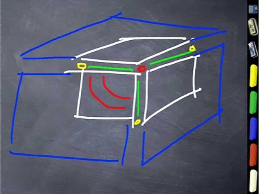
I hope this shows the behaviour i'm experimenting, without having to paste/translate my hottibly confused code. as you may see, the magenta rays, casted from border vertices, don't always hit (i cast them inward and outward, from the center of the sphere.
rays directions are calculated this way:
     var inward = transform.position - vertex;
     var outward = transform.position + vertex;
And this is the detection procedure, for every border vertex
 if (Physics.Raycast (vertex, centro, hit2))
 {
   Debug.DrawLine(vertex, hit2.point, Color.magenta,20);
   vertex= hit2.point; //move this vertex, to the one we hit
 }
   else if (Physics.Raycast (vertex, esterno, hit2))
 {
   Debug.DrawLine(vertex, hit2.point, Color.blue,20);
   vertex = hit2.point;
 }
As you may notice, most vertices are not caught by the raycast
for clarity, here's how the vertices are moved from the sphere
vertex *=(2+(pixelHeight)/5);
where pixelHeight is controlled by my grayscale map reading function.
Just one more note: Instead of spherify a cube(precisely 6 planes) during runtime (which i found rather slow and useless) I actually spherified the plane in my modeling application, may this make some vertex non uniformely spaced ?
thank you, hope to get some feedback, since this is turning out really stimulating for learning.
Are you trying to stitch them together in your modelling program? Or are you actually changing the vertex location within Unity?
I'm trying to stitch them within unity, since the only thing i did in my modelling program was subdividing conveniently a plane.
I'm a bit confused. Are you talking about the solarsystem representation ofa planet or about the close-up, "surface"-view? They are very different in Spore. Also have you and links about the technique used in Spore?
I guess you mean the "surface view" and each "plane" is a part of a spherical segment ?
Well, i guess without some code / screenshots it's hard to say what you're actually trying to do ;)
Yes, I'm actually talking about a surface generation.
I'm following this procedure http://www.nullpointer.co.uk/content/procedural-planets/ the only difference is that I rendered 6 textures, one on each plane, ins$$anonymous$$d of a cubemap, and then mapped them on planes before spheriphying the planet.
and this is spore's whitepaper http://www.andrewwillmott.com/0251-SphericalWorlds-slides.pdf?attredirects=0
As I previously stated,actually I haven't access to my project files, so sadly I can't post a telltale image of what the problem is. I can just describe it: even if the 6 generated textures are perfectly seamless, using them as a heightmap, the sphere has gaps along all borders. (Red edges on the sphere in the image below)
just noticed your answer was moved, and my reply to that disappeared.
Anyway, I'm not using skyboxes for anything else than generating the grayscale image used as an heightmap, but this is done in a separate moment, and on a dummy sphere, and then the skybox is also splitted in 6 different images, before being used as heightmap. so basically, no, i'm not using skyboxes. the problem i'm having, is that raycasting from a border vertex to the center, and in the opposite direction, most of the time, doesn't yeld a collision with another border vertex
So if i understand it right you have to do something like that:

The important thing is that you normalize the original vertex position without the heightmap information. Otherwise the two vertices will be at a different spot since each heightmap is extruded into a different direction. When doing this your seem-vertices will be exactly on top of each other, so a ray through them will go through the center point.
Now that you have calculated the new-grid position in "sphere coordinates" you just add the heightmap information to your sphere radius when you multiply the vector. To avoid gaps, the heightmap value at the seems should be identical on both (or on all three) touching edges.
An example for the top face. We assume that the center is (0,0,0). Each face has a distance from the center of 16, so each face have to be 32x32 in worldspace coordinates. So the plane corners would be:
 (-10, 10,-10)
 (-10, 10, 10)
 ( 10, 10, 10)
 ( 10, 10,-10)
Let's just take the firstposition (-10, 10,-10)
Normalizing would give us something like (-0.577, 0.577,-0.577)
This vector has to be multiplied with your desired sphere radius + the sampled heightmap information for this point. The resulting vector is the new vertex position.
At the seams you would grab the value for both (or at the corners all three) touching planes and take the mean.
Thanks, that's exactly what I was thinking about. $$anonymous$$y only doubt: are seams going to be "flat" this way ? It's still unclear how to average vertices on the borders, if you have any pseudocode (and enough time/interest) I'd be very grateful. i'm gonna give it a try soon, thanks again !
Well, how do you generate the heightmaps? They don't need to be "flat" at the seams (so it doesn't have to be a height value of 0). They just need the same value.
The simplest way is to take the arithmetic mean for two points, one from the each terrain. Just add them up and divide by 2.
That way you won't have a gap, however if the heightmaps don't fit nicely at the seams, you might get sharp spikes. You could include more adjacent values for the smoothing
I generate heightmaps projecting random grayscale brushes on a temporary sphere (pretty much the same radius as the normalized planes) at runtime. then for each face of the cube, apply the heightmap. So basically I need to rewrite this part, making it "detect" edges, and average them... Still unclear HOW :) but i'm thinking about it. Thank you very much, again, for the insight.
hm although your explaination was quite simple, and you precisely hit the spot, I can't manage to get it to work. If you'd like, i can show you my code, so if you have time, you can address me even more precisely.
Thank you again for your help, and have a good day, sir.
The spherification method works fine, but i still have some issues on stitching border vertices: i tried writing a function to parse throught them, and casting a ray to the center and to the outside, hoping the hit.point would be the destination vertex to stitch with, but here behaviour is quite strange and unexpectable: some vertices display such lines, while most of them not.
Here's a much simpler expostion of the MEBNOKISS method
to smooth a cube to a sphere...
write a routine MNK() that takes three blue squares as shown
for each square, look only at the white quarters shown
at the Red point, take the average of the three values.
at the Yellow points, take the midvalue of the two values.
along the green lines. take the midvalue at each point (same as the yellow point)
along the three green lines. simply add a linear function to bring the value at the red end to the red value.
So each white square now has two green "target lines"
For every point P ...
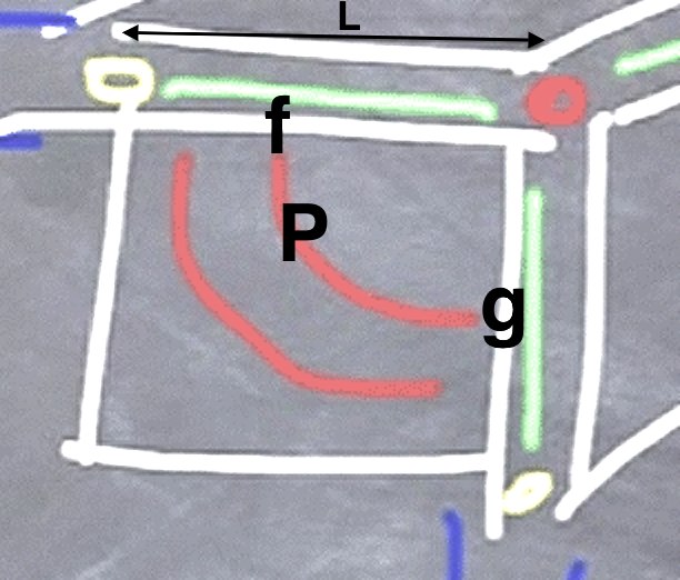
calculate the distance PD from the red point. If bigger than "L" do nothing
using PD, note the pixels f and g
note DF, the delta between green and white at f
note DG, the same at g
slope = ( DG - DF )
get the frangle (fractional angle) of P from f to g. So, if it's 25 degrees it's 25/90==0.2781
as you can see the new value at P is simply
P + DF + (frangle * slope)
DONE
So that'a all there is to it.
Finally -- very carefully arrange to run MNK() eight times for the eight points of the cube.
The simplest trick to achieve this:
rotate the top of the cube four times for the four runs involving the top of the cube. Same for the bottom four runs.
Using this trick, MNK() only has to deal with the one combination of orientations.
Footnotes...
write a convenience function for the green lines: given a number N, simply return the value at the pixel which is N pixels along from the red end.
regarding choosing the pixels f and g. if you prefer, just choose a "fractional" pixel (linear interpolation is fine). so if the value of PD is "57.3". simplest method: just use the value greenpixel57. better method: just use gp57 + 0.3*(gp58-gp57) )
the yellow point is half-way along the blue line starting at the red end. Ideally, program the whole thing so that you can use any fraction there. (eg 0.8 for obvious reasons)
If I understand correctly, you are taking a sphere into 6 segments, sliced like a cube, and projecting a gray heightmap on each, and the problem is at the borders of those heightmaps? Why not average the gray pixels along the borders? If each corresponding border has the same values they should match up pretty well I would think. But I've never tried this type of thing with spheres.
You could also look into using Terrains and get a terrain stitcher from the Asset store.
I would think, yeah, worst case, you would average the vertices along the edges, or again, duplicate them along the edges. Actually, that's more likely. Let's see:
If the top segment duplicated the top edge vertices of the left/right/front/back segments (and similarly for the bottom segment duplicating the corresponding lower edges of those other segments), and then just one edge of each top/right/back/left edge would need to duplicate the vertices of its neighbor, that might work too.
yeah, averaging the border vertice, that was $$anonymous$$y idea. sadly I don't know how
Dave - I assume, like you, that making heightmaps meet is a matter of smearing them, averaging them in.
{I cannot think of any other possible solution, whatsoever: unless you were to say something bizarre like "let's write a general AI that looks at these heightmaps, and compares them to similar surfaces on planet earth, and then makes them mate in a way seen in nature!!!" or something, which is of course utterly absurd and the end result would be .. "averaged together" :O }
regarding annoyingly making three, not two, square images average together. I have presented a relatively trivial approach for so doing in the answer below.
Regarding not the heightmaps but the vertices - as I understand it BUNN has already done the manly job of coding up "transfor$$anonymous$$g from 6 planes to 1 sphere ..... WITH A SLIDER" -- it can be seen in his incredible WEB APP in the link.
how to smear six squares in to one sphere.
Method A "two at a time spinning trick, plus KISS corner trick":
write a left-right smearer, we'll call it LRS( L:SquareImage, R:SquareImage )
it joins the right edge of L with the left edge of R going in say one inch
write a turns 90 degrees CW, we'll call it TCW( X:SquareImage )
we do this ...
// smear using EZ spinning trick
 LRS( front, right )
 LRS( right, rear )
 LRS( rear, left )
 LRS( left, front )

 LRS( top, right )
 TCW(top)
 LRS( top, front )
 TCW(top)
 LRS( top, left )
 TCW(top)
 LRS( top, rear )
 TCW(top)

 LRS( bottom, right )
 TCW(bottom)
 LRS( bottom, rear )
 TCW(bottom)
 LRS( bottom, left )
 TCW(bottom)
 LRS( bottom, front )
 TCW(bottom)
Production note at this stage for unit testing, do just the first four above, and see results on screen. the heightmaps should mate around the girdle of the sphere for the four sides. this checks that the LRS is working fine. of course the top and bottom will meet the four sides in a mess.
the "spin them" trick is easier than writing a smearer that annoyingly has to be able to do any two edges
now they will all meet, other than the last inch of the ones that were done early in the cycle because those would have been disturbed buy the later ones pointing the other way around that corner.
So. "but first"...
Point (-2) write a routine CornerAdjustor(SquareImage) which looks at the top right 1" square of the squareimage...
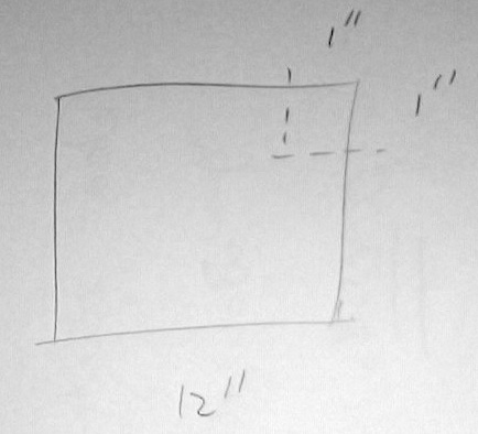
We want the extreme top right point (TRP) to be 0.625. let's say the interesting difference (ID) of the TRP from 0.625 is "+0.137", so ID is +0.137 in the example
for each pixel in the small dotted 1" square. find the mysterious distance (MD) to TRP. if MD is over 1" forget it. otherwise, at that point subtract ( (1.0-MD) * ID )
[footnote] acute readers will notice that ID is the only place we utilise two dimensional distance, so in fact that innocent line of code is the platonic heart of the "two ways how???!" smearing problem.
Point (-1) so do this for each of the six sides
 CornerAdjustor( s )
 TCW(s)
 CornerAdjustor( s )
 TCW(s)
 CornerAdjustor( s )
 TCW(s)
 CornerAdjustor( s )
 TCW(s)
Point (0) because each "last run of pixels" now all end at 0.625 on both ends.... so imagine we are about to smear a NS edge using LRS(). the top and bottom of that NS line (first and last pixels) are indeed 0.625. say you smear inwards two inches on each side (ie, when you run horizontally, we penetrate two inches on either side, let's say). so, when you do the first or final line, in fact, it will, indeed, already meet (indeed at 0.625) so actually nothing, whatsoever, will happen with the first and last (top and bottom) two-inch runs. (the next runs in will be slightly adjusted, and ever more so as you move more inwards from the top and bottom.) So now, one can go ahead and run points (+) 1, 2, 3, 4 above. they will sort of "magically" mesh perfectly at the corners, due to points -2, -1 here.
Now that's all very well, I've realised there's a more elegant way (but not KISS) to do it. I believe the above is the KISS solution.
Note that, of course, instead of using "0.625" simply find the average of all twenty-four corner pixels of the six square images, and use that instead of 0.625.
here's a more elegant but not KISS ("MEB-NOKISS") way to do it:
Method B "MEB-NOKISS":
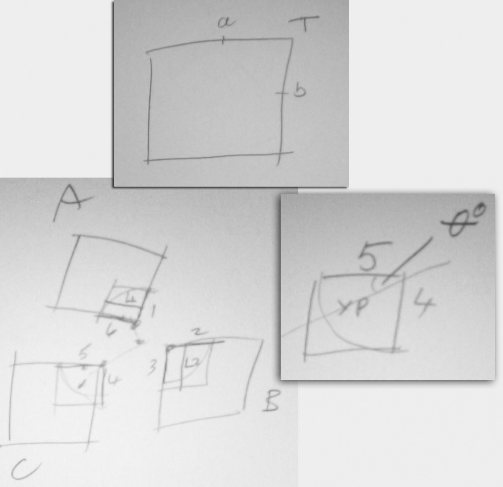
(Point -3) write a routine Half Edge Lines Two Step LinearAdder HELTSLA
HELTSLA( SquareImage, newT:float, newA:float, newB:float )
notice the square in the top diagram. notice the last half-line of pixels from a to T and the last half-line of pixels from b to T
aT now starts at grey value a and ends at grey value T. add a line to it so that it runs from a to newT
same, add a line to bT so it runs from b to NewT
now in the other direction add a line to newTa so that it runs from newT to NewA
same, for newTb, add a line so it runs from newT to newB.
do the to-newT direction first and then do the other direction afterwards
by "add a line" I mean literally add a mathematical line slope x distance, so add "0" to the first pixel increasing linearly to the max delta so that the end becomes the new desired value.
(Point -2) note that HELTSLA operates only on the top-right corner. write a simple wrapper (use TCW from the other reality above) which allows HELTSA to operate on either: top right, top left, or bottom right corner. To achieve this, use the spinning trick explained in the above unrelated method. unit test. don't forget to spin it back after the operation! :)
(Point -1) write a similar trivial helper routine that does this: look at the diagram aTb. the helper routine very simply returns the gray values at a, at T, and at b. again, you have to be able to tell it to "think" using either the top right, top left, or bottom right corner. again use the spinning trick. unit test. don't forget to spin it back after the operation! :)
So we'll call that HELValueGrabber()
(Point 0) create a routine that takes three square images and processes them. We'll call it, um PROTHREE
PROTHREE( A, B, C: SquareImage )
Notice the three squares A B C. Notice the six half-edges 1 2 3 4 5 6
(NOTE - the term "half edge" is a term of art when dealing with 3D mesh. there is utterly no connection here. I just mean it happens to be "half of" the last line of pixels in a square image!!!)
notice all six halfEdgeLines have a Beginning and an End.
all six Ends are simply the one point in the middle. Using HELValueGrabber three times, simply get the average of that point. Let's say it is 0.24715.
Note that your three calls will look something like this:
 HELValueGrabber( A, bottom-right );
 HELValueGrabber( B, top-left );
 HELValueGrabber( C, top-right );
So the new END value for all six halfEdgeLines is 0.24715
For the new BEGIN value for both 1 and 2, simply get the average between the old BEGIN values for 1 and 2. identically for 3,4 and then for 5,6
To repeat 1 and 2 have identical newBegin values, 3,4 have identical newBegin values, and 5,6 have identical new newBegin values. All six simply have the same newEnd value
Now, actually run HELTSLA using those values. Your code should look like this
 HELTSLA( A, bottom-right,      newBegin1,newEnd,newBegin6 );
 HELTSLA( B, top-left,       newBegin3,newEnd,newBegin2);
 HELTSLA( C, top-right,       newBegin5,newEnd,newBegin4);
(to repeat, newBegin1 and newBegin2 are the same number)
(Personally, I would program that to look like this: "Do Heltsa Calculating Values From These Two Wings On My Left And Right", so that PROTHREE would contain only three lines of code, but that's irrelevant.)
(Point 1) so to recap. in the diagram A B C, in fact the halfEdgeLines 1 2 3 4 5 6 are now DONE, they have the final grey values they will ever have.
So now, look at C. Notice the quarter at the top right. We now have to modify the grey values in that top right quarter. So we'll make a routine MODQUARTER( X:SquareImage )
Of course, you must have ALREADY run PROTHREE entirely (on all three) before you run MODQUARTER on any one of them or it is meaningless. (Many good algorithms are temporal.)
So what the hell does MODQUARTER do? Look at the next small diagram of the Quarter in question. Take any point P inside the Quarter. You don't have to do the edges (5 and 4) as they are done.
Get the distance DDDDD of P from the home corner at the top right. If DDDDD is bigger than the length of 5/4, forget about P and do nothing to that pixel.
Get the angle Theta. say 22 degrees. convert to a fractional angle FFFFF of closeness from the line 5. so that would be ( 1.0 - 22/90 ) == 0.8712 FFFFF
Get the pixel, on line 5, distance DDDDD away from the home point. get GrayDelt, the delta between the grey there and at P.
For the pixel at P, add to its gray value: ( GrayDelt * FFFFF )
(To be clear - if P is just about touching 5, it will more or less totally force P to have a value almost the same as that value on 5. If P is further away, it will strongly push P towards that value. if P is quite far away, it will nudge P a little but towards that value.)
Now do the same thing ....... going the other way towards 4.
{Aside - you might wonder, what the hell happens to the omitted slice? isn't there the possibility of an abrupt change? NO - because we already smeared them in a certain way earlier, precluding any abrupt changes now.}
(Point 2) As usual, make MODQUARTER understand that it can do either the topright, bottomright or topleft quarter of a SquareImage. And then do this
 MODQUARTER( A, bottom-right );
 MODQUARTER( B, top-left );
 MODQUARTER( C, top-right );
(Point 3) Looking at the diagram A B C. Imagine a cube where indeed A is the top face, C is the front face and B is the right face. Construct a Grand Routine...
DoThisPointySection( A, B, C: SquareImages )
where indeed A B C are oriented as in the sketch above and as in the discussion above. Now get very very sober to do this:
 DoThisPointySection( top, right,front)
 TCW(top)
 DoThisPointySection( top, rear,right)
 TCW(top)
 DoThisPointySection( top, left,rear)
 TCW(top)
 DoThisPointySection( top, front,left)
 TCW(top) // (returns it to normal!)
Now unit test and you will see the top half of the sphere mate smoothly and beautifully.
Note that those four lines of code do all the "top quarters" of the four side faces. (That's why each side face gets called twice in those four lines of code.)
Now do this TCW twice for all the side faces, then do the same four lines of code using the bottom face instead of the top face, and that will do the bottom. (in other words, turn the cube profoundly upside down, and do the same thing again.)
Again ... the alternative to all this spinning, is, you would have to write an absurdly complicated DoThisPointySection routine that has arguments along the lines of ... DoThisPointySection( A, which quarter, B, which quarter, C, which quarter ) rather than our elegant DoThisPointySection( A B C ).
:) Haven't you seen my comment on the question above? I posted an webplayer link of my current state
Webplayer link ......INCREDIBLE.
re making the heightmaps smear nicely
I have deleted this very long comment, as I typed out my $$anonymous$$ISS SUGGESTED $$anonymous$$ETHOD in the answer.
i must say that i really need to read again the whole thing, because it just went over and over above my head.
If i got this one correctly, are you suggesting a "numeric" criteria to find matching vertices on faces ? that may be feasable, since my plane is instanced, and rotated via script, so basically i can keep track of a face position/rotation, but still, i have no clue on implementing it. as soon as i have some spare time, i'll try to progress. thank you !
I'm actually on something similar to your first method ;) I made a coordinate wrapper (actually 3, sure you could stack one 3 times but it's bad for performance ;) ). I wanted a method which allows you to address any position on the sphere including it's neighbors out-of-the-box. So for every plane i have a "virtual space" which goes across the planes own borders and map to the correct coordinates on the neighbor plane.
I directly address the vertices of the meshes. Couldn't find a good solution for returning the right plane and vertex index at the same time.
I'm still quite busy but maybe i have some time this weekend ;)
ok i posted a dramatically simplified explanation of method2 !!
Hello, i'm back on topic :) sorry for being late, but this is something i'm working on in my spare time. and I hadn't much, lately. (oh and a bit of despair, because of the amazing webplayer demo by bynny83:)
Although i've read you reply (many times) i realized never thanked you, Fattie, for putting so much effort in such an explaination which is, sadly, a bit beyond my math/programming skills. but anyway, of course was an inspiration for the method i'm showing.
let's take for example the connection between the front face, and right one:
Just after the extrusion phase of the heightmap, i fill up 4 arrays for each cube face, one for each edge.
Right_RIGHT_EDGE.Add(cube_faces[orientation].transform.TransformPoint(vertex));
("cube_faces" is an array containing my 6 instanced "slices" of sphere, and "orientation" is an utility counter to call for them: so that i can make a for and apply my functions within it
then accordingly, the average is computed
 tempvector1= cube_faces[0].transform.TransformPoint(front_LEFT_EDGE[i]);
 tempvector2= cube_faces[0].transform.TransformPoint(right_RIGHT_EDGE[i]);
 mid_front_right[i]= (tempvector1+tempvector2)/2;
now, cube_faces[0] used as transform.TransformPoint origin, yelds the correct results for all the faces, except the top and the bottom one, but we'll deal with that later.
finally, parsing again the vertices of the mesh
... if(x==mesh.maxvertices) {
                     if (LEFT_EDGE_count==128)
                     {
                     LEFT_EDGE_count=0;
                     }

                     if(orientation ==1)
                         {
                         vertex = cube_faces[orientation].transform.InverseTransformPoint(mid_front_right[LEFT_EDGE_count]);
                         LEFT_EDGE_count++;
                         }
and
                     if(x==mesh.minvertices)
                         {

                         if (RIGHT_EDGE_count==128)
                         {
                         RIGHT_EDGE_count=0;
                         }

                         if(orientation ==0)
                             {
                             vertex = cube_faces[orientation].transform.InverseTransformPoint(mid_front_right[RIGHT_EDGE_count]);
                             RIGHT_EDGE_count++;
                             }
...
And this way, by trial and errors, i managed to make terrains stitch together. but when i try to apply the same technique to the top or bottom slice, it's somehow unpredictably computing the mids, wrongly. I guess it's something to do with the "transform.TransformPoint"
"transform.InverseTransformPoint"
part of the procedure. i made a debug function instantiate spheres on: each seam vertex, plus one in the average position, and while the first two of them are correctly following the vertices positions along the chosen edge, the average is in an unpredictable position.
now, i don't know if i have to go deeper in details, since in the "two at a time spinning trick, plus KISS corner trick" method you suggested me, you assumed top and bottom will be a mess and should be dealt with separately. hope you can help me solving my problem within my naive implementation :)
also, being thrilled by the success of stitching most of it together, i noticed that normals aren't consistent through stitched faces, even if a called
mesh.RecalculateNormals();
after the seams stitching function. but that's something minor :)
Thank you guys for your time and inputs !
regarding normals .. here's a depressing bit of news, I doubt Unity's RecalculateNormals will work for you in this case ...
http://answers.unity3d.com/questions/329116/do-we-need-to-call-recalculatenormals-if-normal-ve.html
essentially I've only ever done me' own normals in non-trivial cases. I'm not sure if the unity routine is even in the ballpark of giving a reasonable result here? Perhaps @Bunn has an answer on that one? Should recalculateNormals give an even reasonable result in a case like this?
Now is it correct that you are able to do the front-right join .. is that right?
But you're having trouble with the say front-top join ?
Hello ! Yes, i do have problems everytime i want to join a section, with the upper one or the lower one. I'm quite sure it's something I did wrong with the TransformPoint/InverseTransformPoint procedure, which works fine for front/back and left/right, but doesn't apply to the top bottom face. Thanks !
