Controlling roll rotation when travelling along bezier curves
I am currently working on implementing a curves implementation which includes an editor:
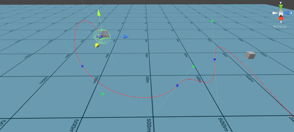
The aim is to get an object to follow the path represented by the curve at a constant velocity. Currently you can place nodes in the curve and modify the weights of each node via handles to control the curve segments between nodes. The curve implementation is a standard bezier curve.
It works as described except that sometimes the rotation of the object along the path is not great. For instance doing a vertical loop can cause the object to flip over at certain points suddenly. I am currently setting the rotation of the object as follows:
transform.LookAt(bezier(waypoints, handles, lookAhead));
This is computing the point in the curve slightly ahead of the current point and setting the object to "look at" that point. The pitch and yaw of the object will therefore be correct but the roll cannot be easily controlled.
I am currently trying to implement a way to control the roll as the object travels along the path but my maths skills are failing me once again. In the editor I am thinking of placing "roll" nodes along the path which represent the desired roll angle of the object when it reaches that node and interpolating between these nodes for the points in between. My questions are as follows:
How would you determine the yaw and pitch manually at each point? My objects are airplanes so they will always be facing "forward".
How would you know the direction to turn towards to get to the next nodes roll angle? It could be anticlockwise or clockwise I assume. Would I need to also add a control to say which way to turn?
How would I determine what is "up" to orientate myself when controlling the roll angle of the objects along the path?
EDIT:
Example: https://www.youtube.com/watch?v=0BHGoKOIQa0&feature=youtu.be
The linked youtube video shows the problem I am experiencing with using
transform.LookAt(bezier(waypoints, handles, lookAhead));
alone to control the rotation Quaternion. Watch the plane object rotate when looping vertically. The box sticking out is on the top of the plane object.
When the object reaches the point when it should be "upside down" in the loop it spins quickly to be the facing upwards again. If I can make it so that the up vector of the object along the path follows the "natural" rotation along the curve I can then apply quarternion control points to properly control rotation. Sorry if this is not entirely clear, I don't know the proper terminology for a lot of this stuff.
You could store not only a position for each control point, but also a rotation (Quaternion), which resembles the rotation that the UP vector has to rotate to create the local up vector at that control point. You could draw this local up vector as a small line originating from the CP and going into the direction of the controlPointRotation * Vector3.up vector.
Then you can just interpolate the rotation quaternion between control points, depending which curve segment you are currently sampling. Quaternion SLERP also always takes the shortest path rotation, so you don't have to worry about specifying a rotation direction.
If you need that though, you have to thrash the quaternion and use a Vector3 which represents euler angles instead. Euler angles can represent relative rotations greater than 180° and thus are better suited to model multiple revelations between two control points. But they have the disadvantage that they don't interpolate as smoothly as quaternions do.
Thanks for the reply, I think I sort of get what you are suggesting. I can create interpolated quaternion (based on control quarternions to rotate my current transform rotation I have after calling the LookAt.
The current problem I am running into is as follows though, since the LookAt always uses Vector3.up to deter$$anonymous$$e the quarternion it means that my objects always "flip" when they vertically loop. I have added a link to youtube to my original qs which illustrates this problem.
Yeah, I know that problem :) That's why I suggested you define your own "up" vectors at every CP by using a rotation quaternion to represent the rotation of your custom up vector relative to the "standard" (0,1,0) up-vector. If you have a curve segment from CP0 to CP1 and you have two quaternions defined at CP0 and CP1, namely CP0r and CP1r, and you have a value t which is in the range of [0;1] and defines the progress between CP0 and CP1 then you can figure out your custom up vector by doing Vector3 localUp = Quaternion.Slerp(CP0r, CP1r, t) * Vector3.up
Actually you won't need your LookAt at all, if you can compute the second derivative of the bezier curve you already have two axes of your local orthogonal coordinate system (up/Y and forward/Z). You just have to compute Right/X (cross product) and orthogonalize the coordinate system (simply re-compute Y or Z by doing another cross with the Y axis and X or Z). With this you can compute a rotation matrix ;-)
Ahhh! It finally clicked after your explanation. This sounds like it will work for me. I am going to implement this now. Thanks for the replies!
