How come my code-created cuboids visually have no distinct edges?
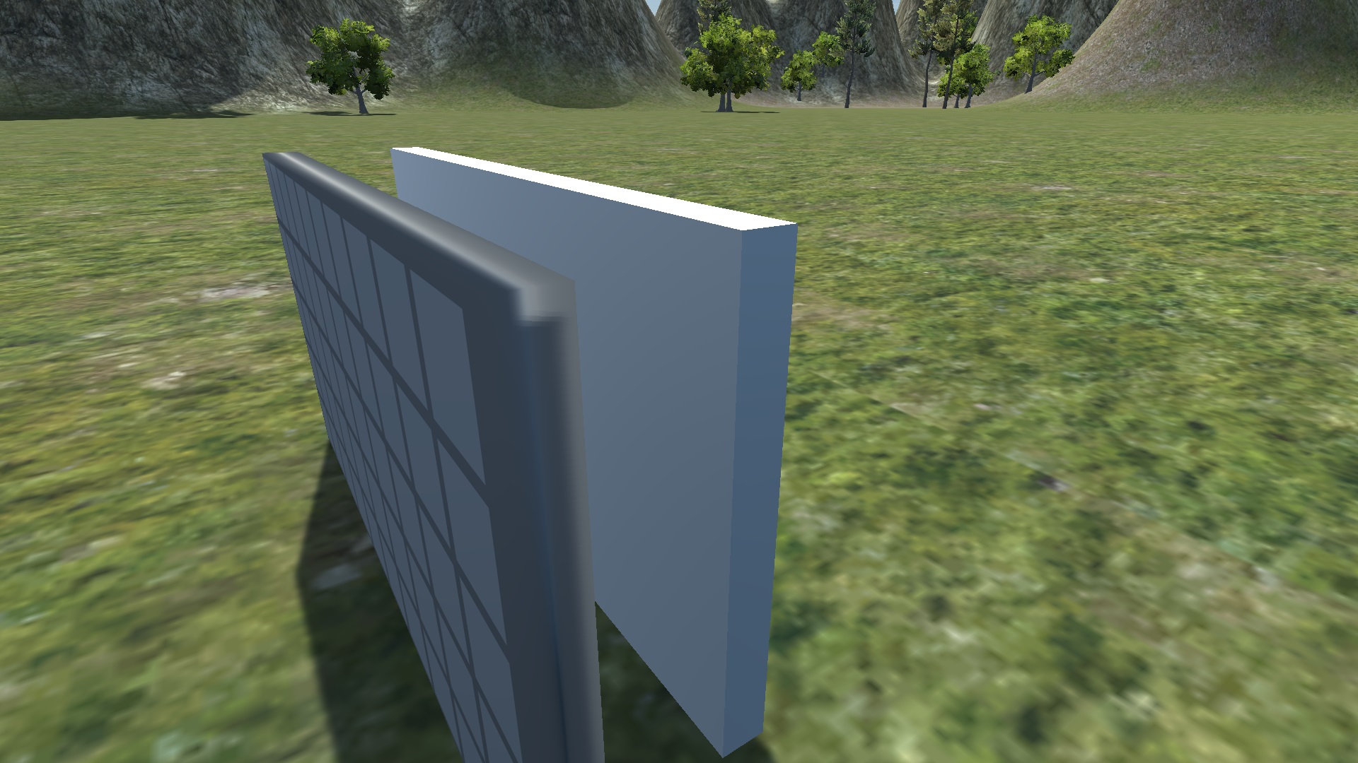
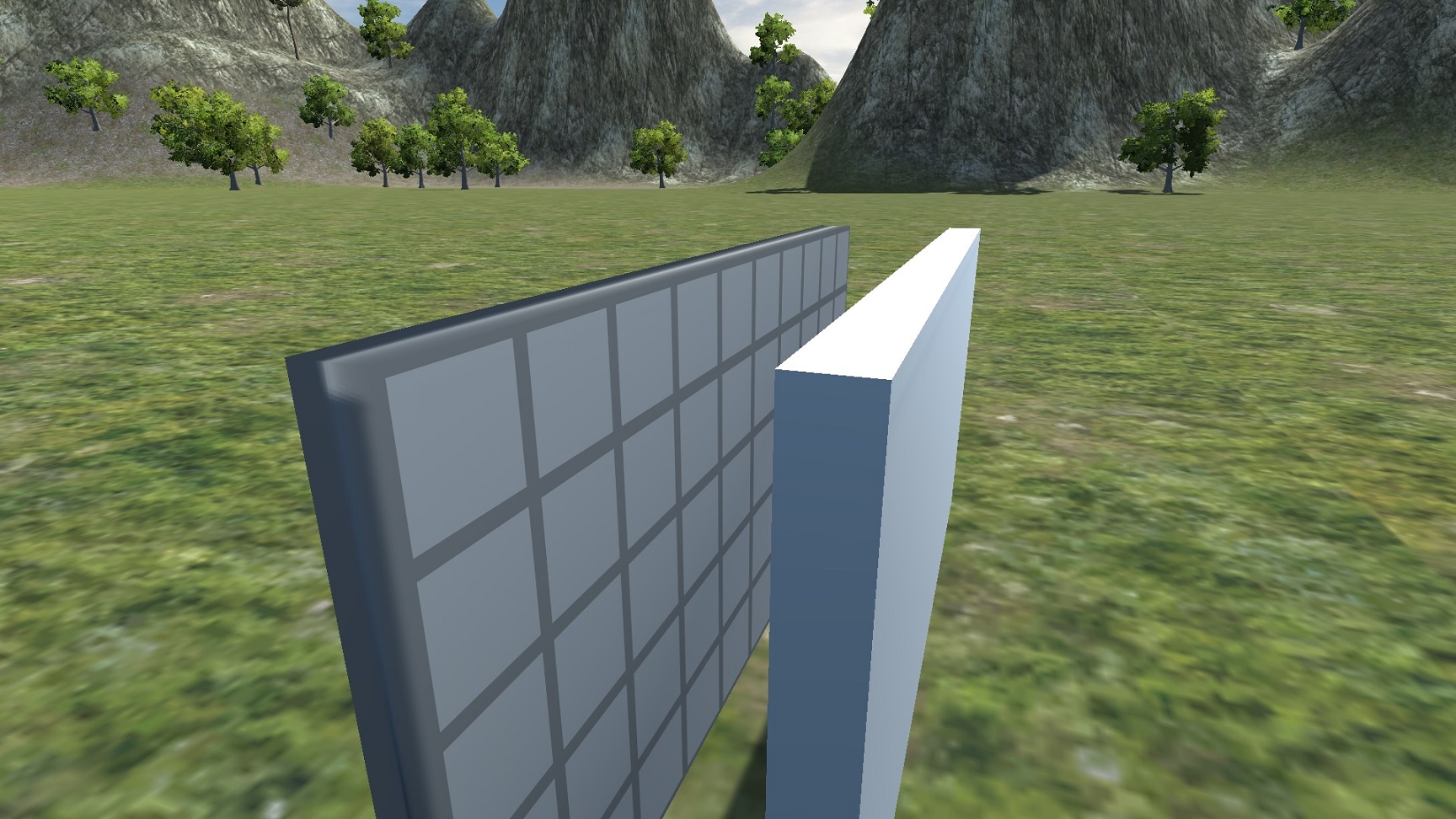
Sorry for the bad title, the issue is hard to describe with words. Here are some pictures. The cuboid I created with code is the one with the grid on it. The white one next to it is a standard Unity primitive cube set to the same scale for comparison.
And here's the code I'm using to generate the custom mesh:
     public int x;
     public int z;

     public BoxCollider ThisCollider;
     public Renderer ThisRenderer;

     public void CreateCuboid()
     {
         Vector3[] vertices = {
             new Vector3 (0, -0.5f, 0) * 0.15f, // each element is *0.3 because that's what I've decided the global scale shall be, and then by 0.5 because idk it just works
             new Vector3 (2 * x, -0.5f, 0) * 0.15f,
             new Vector3 (2 * x, 0.5f, 0) * 0.15f,
             new Vector3 (0, 0.5f, 0) * 0.15f,
             new Vector3 (0, 0.5f, 2 * z) * 0.15f,
             new Vector3 (2 * x, 0.5f, 2 * z) * 0.15f,
             new Vector3 (2 * x, -0.5f, 2 * z) * 0.15f,
             new Vector3 (0, -0.5f, 2 * z) * 0.15f,
         };

         int[] triangles = {
             0, 2, 1, //face front
             0, 3, 2,
             2, 3, 4, //face top
             2, 4, 5,
             1, 2, 5, //face right
             1, 5, 6,
             0, 7, 4, //face left
             0, 4, 3,
             5, 4, 7, //face back
             5, 7, 6,
             0, 6, 7, //face bottom
             0, 1, 6
         };

         Mesh mesh = GetComponent<MeshFilter>().mesh;
         mesh.Clear();
         mesh.vertices = vertices;
         mesh.triangles = triangles;

         // I suspect this section is why the shading is borked. I don't actually know what UVs are or how to use them, this code is straight up copied from the Unity manual
         Vector2[] uvs = new Vector2[vertices.Length];
         for (int i = 0; i < uvs.Length; i++)
         {
             uvs[i] = new Vector2(vertices[i].x, vertices[i].z);
         }
         mesh.uv = uvs;

         mesh.RecalculateNormals();
     }
Can someone help me make my cuboids look normal?
The problem is with Normals. Unity's primitive cube has 24 vertices: 4 vertices for each of the 6 faces of a cube (3 vertices for each cube corner). The two triangles of each face use their own face's vertices. The normals for each face (one normal per vertex) are set to the same direction: perpendicular to the face.
What you've done is create a box with 8 vertices: one for each of the 8 corners of a box. Then you re-used those vertices for the triangles on different faces of the box. Then when you call mesh.RecalculateNormals() it thinks each vertex is on a smooth face, so each normal points away from the centre of the box, not perpendicular to any one face.
Note: You can manually set vertex normals by creating a mesh.normals array after creating the mesh.vertices array.
Right +1.
Though it's not only the normals but also the UV coordinates for each face. All vertex attributes are specitied per vertex. If any of those attributes should be different for two or more faces at the same vertex you have to split the vertex into seperate vertices. So they have the same "position" attribute but may have different normals / tangents, UV coordinates, vertex colors.
$$anonymous$$any 3d artists don't understand this as they only work with "logical vertices" in modelling tools. However this is how the GPU actually processes the mesh data. $$anonymous$$odelling tools are ment to simplify the editing. It would be a pain to drag 3 seperate vertices around
edit
Over here i have some compact way to create a "cuboid". Well i actually created a mesh for the camera frustum. You can just ignore the first for loop which does the projection in camera space. I also specify 8 vertices which are then split into 24 by code.
Thank you so much, it works!!

I fixed it by replacing the vertexes and triangles arrays with the following:
         Vector3[] vertices = {
             // set 1
             new Vector3 (0, -0.5f, 0) * 0.15f, // each element is *0.3 because that's what I've decided the global scale shall be, and then by 0.5 because idk it just works
             new Vector3 (2 * x, -0.5f, 0) * 0.15f,
             new Vector3 (2 * x, 0.5f, 0) * 0.15f,
             new Vector3 (0, 0.5f, 0) * 0.15f,
             new Vector3 (0, 0.5f, 2 * z) * 0.15f,
             new Vector3 (2 * x, 0.5f, 2 * z) * 0.15f,
             new Vector3 (2 * x, -0.5f, 2 * z) * 0.15f,
             new Vector3 (0, -0.5f, 2 * z) * 0.15f,

             // set 2
             new Vector3 (0, -0.5f, 0) * 0.15f,
             new Vector3 (2 * x, -0.5f, 0) * 0.15f,
             new Vector3 (2 * x, 0.5f, 0) * 0.15f,
             new Vector3 (0, 0.5f, 0) * 0.15f,
             new Vector3 (0, 0.5f, 2 * z) * 0.15f,
             new Vector3 (2 * x, 0.5f, 2 * z) * 0.15f,
             new Vector3 (2 * x, -0.5f, 2 * z) * 0.15f,
             new Vector3 (0, -0.5f, 2 * z) * 0.15f,

             // set 3
             new Vector3 (0, -0.5f, 0) * 0.15f,
             new Vector3 (2 * x, -0.5f, 0) * 0.15f,
             new Vector3 (2 * x, 0.5f, 0) * 0.15f,
             new Vector3 (0, 0.5f, 0) * 0.15f,
             new Vector3 (0, 0.5f, 2 * z) * 0.15f,
             new Vector3 (2 * x, 0.5f, 2 * z) * 0.15f,
             new Vector3 (2 * x, -0.5f, 2 * z) * 0.15f,
             new Vector3 (0, -0.5f, 2 * z) * 0.15f,
         };

         int[] triangles = {
             // using set 1
             0, 2, 1, //face front
             0, 3, 2,
             5, 4, 7, //face back
             5, 7, 6,

             // using set 2
             10, 11, 12, //face top
             10, 12, 13,
             8, 14, 15, //face bottom
             8, 9, 14,

             // using set 3
             17, 18, 21, //face right
             17, 21, 22,
             16, 23, 20, //face left
             16, 20, 19,
         };
