Wayback Machinekoobas.hobune.stream
May JUN Jul
Previous capture 12 Next capture
2021 2022 2023
1 capture
12 Jun 22 - 12 Jun 22
sparklines
Close Help
  • Products
  • Solutions
  • Made with Unity
  • Learning
  • Support & Services
  • Community
  • Asset Store
  • Get Unity

UNITY ACCOUNT

You need a Unity Account to shop in the Online and Asset Stores, participate in the Unity Community and manage your license portfolio. Login Create account
  • Blog
  • Forums
  • Answers
  • Evangelists
  • User Groups
  • Beta Program
  • Advisory Panel

Navigation

  • Home
  • Products
  • Solutions
  • Made with Unity
  • Learning
  • Support & Services
  • Community
    • Blog
    • Forums
    • Answers
    • Evangelists
    • User Groups
    • Beta Program
    • Advisory Panel

Unity account

You need a Unity Account to shop in the Online and Asset Stores, participate in the Unity Community and manage your license portfolio. Login Create account

Language

  • Chinese
  • Spanish
  • Japanese
  • Korean
  • Portuguese
  • Ask a question
  • Spaces
    • Default
    • Help Room
    • META
    • Moderators
    • Topics
    • Questions
    • Users
    • Badges
  • Home /
  • Help Room /
avatar image
0
Question by anirudhna · May 07, 2017 at 09:29 PM · meshnormalsprocedural meshcalculation

Is it possible to use face normals as vertex normals in procedurally generated meshes?

Hi All,

I have a problem with getting the normals right on a procedurally generated mesh in my project. I will attempt to clarify the steps I am following:

  • I have a 3dCAD model (.ifc file) of a building that i parse using an external library (xBIM) and obtain the vertice of the mesh and the triangle indices array (mesh. vertices and mesh. triangles)

  • Let's say that I have a wall with 6 faces (cuboid). When I parse the triangulation of this wall, I obtain 8 vertices and the 3 triangle vertices per triangle per face (i.e 2 triangles per face * 6 faces = 12 triangles. 3 vertices per triangle and hence 12*3 = 36 indices)

  • I use these as the arrays as mesh.vertices ( Vector3 , length 8) and mesh.triangles (int[], length36)

  • At this point I get the mesh right in Unity (the geomertry is correctly replicated), but the shading is bad and the edges of the shape are not visible.

  • Unfortunately, the library I am using gives the face normals instead of the vertex normals. Which means that per geometry (of 6 faces) I get a normal array of 6 members.

  • How do I use these normals to assign the normals to vertices so as to have a correctly displayed mesh in Unity?

Currently I am using the triangles array to compile an elaborate vertices array (using the 8 vertex points in an ordered manner of 36 points to define the 6 vertices that define each of the 6 faces of the cuboid), something similar to the what is done here .

Therfore, my vertices array is now 36 * Vector3 members long. In an attempt to assign normals to these vertices, I used the face normal I obtained and then assigned the same normal to all the vertices that are deining that face. For e.g, vertices 0,1,2,1,0,3 define the 2 triangles of the front face of the cuboid. I used the face normal obtained for this face and assigned that as the normal vector for each of the vertex.

Anyway, I get a strange result and the front faces of the geometries are culled.

The issue is the same even if I use mesh.RecalculateNormals() method instead of assigning the normals at all to the mesh.

Is there something I am missing/ doing wrong in assigning the normals/vertices that the mesh is incorrectly rendered? Btw, I also tried reversing the order of mesh.trianglesa array, but the result was same.

Please help. I apologize for the verbose question, but I hope it explains my problem.

alt text 
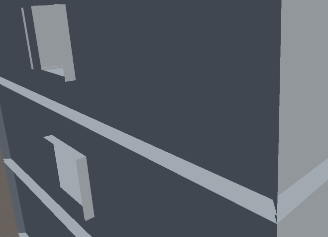
The mesh hhighlighted is invisible but the geometry is alright when viewed from the opposite side.

alt text 
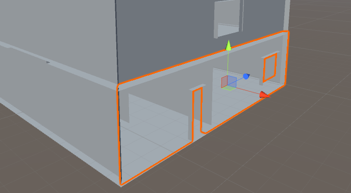
The front faces of these cuboid (wall) geometries are culled.

The part of code I am using to assign the mesh data is as follows. The vertices and triangles arrays are parsed from an XML file:

             GO.AddComponent<MeshFilter>();
             GO.AddComponent<MeshRenderer>();
             Mesh mesh = GO.GetComponent<MeshFilter>().mesh;

             mesh.Clear();

             Vector3[] mod_Verts = new Vector3[meshTriangles.Count]; 
             //meshtriangles.count is 36 // meshtriangles is the list of indices used as  mesh.triangles 
             int[] mod_Triangles = new int [meshTriangles.Count];

             for (int x = 0; x < mod_Verts.Length; ++x)
             {
                 mod_Verts[x] = meshVertices[meshTriangles[x]]; // extends vertices array to define vertices 
                 for each face

                 Debug.Log(GO.name + "_"+ x + "_" + mod_Verts[x] + " | " + " Vert_No: " +               
                 meshTriangles[x]);

                 mod_Triangles[x] = x;
                 
             }
             
             
             mesh.vertices = mod_Verts;
             
             mesh.triangles = mod_Triangles;

             mesh.RecalculateBounds();

             //mesh.normals = meshnormals.ToArray();

             mesh.RecalculateNormals();


Many thanks in Advance, Ani

2.png (11.3 kB)
1.png (38.1 kB)
Comment
Add comment · Show 2
10 |3000 characters needed characters left characters exceeded
▼
  • Viewable by all users
  • Viewable by moderators
  • Viewable by moderators and the original poster
  • Advanced visibility
Viewable by all users
avatar image anirudhna · May 08, 2017 at 09:59 PM 0
Share

Ok, After investigating, I found out that the winding order of the vertices per face is not consistent. I am working on checking in set of 3's the vertices and deter$$anonymous$$e if the winding order is wrong and rectify it. In the mean time, if anybody has already worked out a solution to the same, pls do dhare and advise!

Thanks, Ani

avatar image ohkyounghwan · Jan 24, 2018 at 06:53 AM 1
Share

I would like to ask you one thing. I wonder if you have imported the geometry information using the xbim library in Unity 3D.

1 Reply

· Add your reply
  • Sort: 
avatar image
0

Answer by dmitriy-untilov · Feb 01, 2018 at 04:31 PM

You can try to swap Y and Z coordinate of each vertex, because coordinate systems in CAD and Unity are differ.

Comment
Add comment · Share
10 |3000 characters needed characters left characters exceeded
▼
  • Viewable by all users
  • Viewable by moderators
  • Viewable by moderators and the original poster
  • Advanced visibility
Viewable by all users

Your answer

Hint: You can notify a user about this post by typing @username

Up to 2 attachments (including images) can be used with a maximum of 524.3 kB each and 1.0 MB total.

Follow this Question

Answers Answers and Comments

108 People are following this question.

avatar image avatar image avatar image avatar image avatar image avatar image avatar image avatar image avatar image avatar image avatar image avatar image avatar image avatar image avatar image avatar image avatar image avatar image avatar image avatar image avatar image avatar image avatar image avatar image avatar image avatar image avatar image avatar image avatar image avatar image avatar image avatar image avatar image avatar image avatar image avatar image avatar image avatar image avatar image avatar image avatar image avatar image avatar image avatar image avatar image avatar image avatar image avatar image avatar image avatar image avatar image avatar image avatar image avatar image avatar image avatar image avatar image avatar image avatar image avatar image avatar image avatar image avatar image avatar image avatar image avatar image avatar image avatar image avatar image avatar image avatar image avatar image avatar image avatar image avatar image avatar image avatar image avatar image avatar image avatar image avatar image avatar image avatar image avatar image avatar image avatar image avatar image avatar image avatar image avatar image avatar image avatar image avatar image avatar image avatar image avatar image avatar image avatar image avatar image avatar image avatar image avatar image avatar image avatar image avatar image avatar image avatar image avatar image

Related Questions

Weird Artifacts in Mesh generated by Script 1 Answer

Some triangles are black on a mesh generated by script 1 Answer

Calculate Normals that pointing outside 0 Answers

How To Find Meshes Without Normals for Global Illumination? 2 Answers

Procedural mesh shader problem 0 Answers


Enterprise
Social Q&A

Social
Subscribe on YouTube social-youtube Follow on LinkedIn social-linkedin Follow on Twitter social-twitter Follow on Facebook social-facebook Follow on Instagram social-instagram

Footer

  • Purchase
    • Products
    • Subscription
    • Asset Store
    • Unity Gear
    • Resellers
  • Education
    • Students
    • Educators
    • Certification
    • Learn
    • Center of Excellence
  • Download
    • Unity
    • Beta Program
  • Unity Labs
    • Labs
    • Publications
  • Resources
    • Learn platform
    • Community
    • Documentation
    • Unity QA
    • FAQ
    • Services Status
    • Connect
  • About Unity
    • About Us
    • Blog
    • Events
    • Careers
    • Contact
    • Press
    • Partners
    • Affiliates
    • Security
Copyright © 2020 Unity Technologies
  • Legal
  • Privacy Policy
  • Cookies
  • Do Not Sell My Personal Information
  • Cookies Settings
"Unity", Unity logos, and other Unity trademarks are trademarks or registered trademarks of Unity Technologies or its affiliates in the U.S. and elsewhere (more info here). Other names or brands are trademarks of their respective owners.
  • Anonymous
  • Sign in
  • Create
  • Ask a question
  • Spaces
  • Default
  • Help Room
  • META
  • Moderators
  • Explore
  • Topics
  • Questions
  • Users
  • Badges