How to create a smooth gradient shader for bumpy terrain
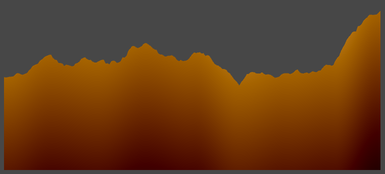
I'm creating a simple shader to add a gradient to 2D terrain that is generated at runtime, and I want the gradient to follow the terrain, if that makes sense. It works on a smooth hill like this:

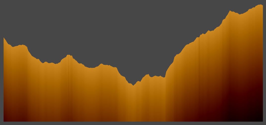
The problem is on more rocky terrain, it shows a lot of vertical banding as it tries to follow the terrain:
Here is the shader code. It uses UV2 for the gradient, UV1 is used for a texture but I've taken that out so this is just the gradient part:
 Shader ".Custom/Terrain Gradient"
 {
     Properties
     {
         _Color("Color", Color) = (1,1,1,1)
         _GradBalance("Gradient Brightness Balance", Float) = 1
         _GradStrength("Gradient Strength", Float) = 1.2
     }

     SubShader
     {
         Pass
         {
             CGPROGRAM

             #pragma vertex vertexFunction
             #pragma fragment fragmentFunction

             #include "UnityCG.cginc"

             struct appdata {
                 float4 vertex : POSITION;
                 float2 uv2 : TEXCOORD1;
             };

             struct v2f {
                 float4 vertex : SV_POSITION;
                 float2 uv2 : TEXCOORD1;
             };

             float4 _Color;
             float _GradBalance;
             float _GradStrength;

             v2f vertexFunction(appdata IN)
             {
                 v2f OUT;

                 OUT.vertex = UnityObjectToClipPos(IN.vertex);
                 OUT.uv2 = IN.uv2;

                 return OUT;
             }

             fixed4 fragmentFunction(v2f IN) : SV_TARGET
             {
                 float4 finalColor = _Color;

                 finalColor = _Color + ((IN.uv2.y - _GradBalance) * _GradStrength);

                 return finalColor;
             }

             ENDCG
         }
     }
 }
Here is how the UV2 is generated for the terrain. It takes the heightmap, which is just an array of floats for the location of each vertex across the top of the terrain, and the resolution, which is how many vertices per Unity unity (i.e. resolution of 1 means each vertex is one unit apart, 2 means each vertex is 0.5 units apart, etc.), and creates a UV point for the top and bottom of the terrain:
 static Vector2[] GenerateTerrainUV2(float[] heightMap, int resolution)
 {
     Vector2[] uv = new Vector2[heightMap.Length * 2];

     float texSize = heightMap.Length - 1f;

     // For each point in the heightMap, create a UV location for the top and bottom of the terrain
     for (int i = 0; i < heightMap.Length; i++)
     {
         // For the UV X value, the left side of the terrain is 0 and the right side is 1
         // For the UV Y value:

         // Y is 1 across the top of the terrain
         uv[i * 2] = new Vector2(i / texSize, 1);

         // and Y is an equal amount below the top of the terrain as the terrain is wide
         uv[i * 2 + 1] = new Vector2(i / texSize, ((heightMap[i] * resolution) - texSize) / -texSize);

         // "((heightMap[i] * resolution) - texSize) / -texSize" means that, for example, if the terrain is 100 units wide:
         // If the value of the heightMap at one point is 0, the Y for the UV at the bottom would be 1
         // If the value of the heightMap at one point is 100, the Y for the UV at the bottom would be 0
         // If the value of the heightMap at one point is 200, the Y for the UV at the bottom would be -1
     }
 }
How can I improve this or what can I do differently to remove the banding?
Project available here: https://github.com/karlludwinski/2D-Terrain-Generation
I am trying to set up your scripts in an empty project but not sure how to generate the mesh. Could you post some more code?
Sure thing, here's a project you can use:
Ty for code. I tried around some things but couldn't get things smooth. Still not sure excatly what you want it to look like. I think the banding is just the effect of the linear interpolation you are doing. I see you are using midpoint displacement for your terrain. If you ins$$anonymous$$d switched to using fractal noise with multiple octaves. I imagine you could stop after one or two octaves and calculate the uvs based on those vertices. Then continue a couple more octaves. That way you would have smoother coloring that follows the general shape of terrain but the terrain can still be as rough as you have it. Goodluck
Ended up working around it by generating a secondary set of UV points using the first couple points generated using midpoint displacement, then cosine interpolating between those and calculating the offset between those and the actual terrain points:
Updated UV2 method:
 static Vector2[] GenerateTerrainUV2(float[] heightMap, int resolution, TerrainMethodType terrainMethodType)
     {
         Vector2[] uv = new Vector2[heightMap.Length * 2];

         float texSize = heightMap.Length - 1f;

         if (terrainMethodType == TerrainMethodType.RockyMountains)
         {
             /*
              * When the terrain type is RockyMountains, the gradient shader has a lot of vertical banding due to the
              * abrupt changes in height from one point to another. What we do to counter this is generate a secondary
              * smoother heightmap for the UV.
              *
              * This is done by taking the first few points generated by the midpoint displacement and cosine interpolating
              * between them, so that there is a smooth line that roughly follows the major points of the terrain.
             */

             float[] uvHeightMap = (float[])heightMap.Clone();

             // Array to store the heightMap indexes of the control points that we will interpolate between
             // This stores 9  values: the index of the start and end, and the first 7 points generated by midpoint displacement
             int[] controlPointsLocationIndex = new int[9];

             // Set the start and end manually as we know those are the first and last points of the array
             controlPointsLocationIndex[0] = 0;
             controlPointsLocationIndex[controlPointsLocationIndex.Length - 1] = uvHeightMap.Length - 1;

             // Find the 7 points between the start and end
             float currentIndexValue = uvHeightMap.Length - 1;
             float stepSize = (uvHeightMap.Length - 1) / 8f;

             for (int i = 7; i > 0; i--)
             {
                 currentIndexValue -= stepSize;

                 controlPointsLocationIndex[i] = (int)Mathf.Floor(currentIndexValue);
             }

             int nextIndexLocation = 1;

             // Iterate through the heightMap..
             for (int i = 1; i < uvHeightMap.Length - 1; i++)
             {
                 if (i >= controlPointsLocationIndex[nextIndexLocation])
                 {
                     nextIndexLocation++;
                 }

                 // and determine the Y value for each point between the control points using cosine interpolation
                 uvHeightMap[i] = CosineInterpolate(uvHeightMap[controlPointsLocationIndex[nextIndexLocation - 1]],
                     uvHeightMap[controlPointsLocationIndex[nextIndexLocation]],
                     (i - (float)controlPointsLocationIndex[nextIndexLocation - 1]) / ((float)controlPointsLocationIndex[nextIndexLocation] - controlPointsLocationIndex[nextIndexLocation - 1]));
             }

             int terrainWidth = (int)texSize / resolution;

             // Loop through heightmap and create a UV point for the top and bottom.
             for (int i = 0; i < heightMap.Length; i++)
             {
                 float uvY = 1f - ((uvHeightMap[i] - heightMap[i]) / terrainWidth); // calculate difference between heightMap value and uvHeightMap value

                 // Creates a gradient starting at the top of the terrain that goes past the bottom
                 uv[i * 2] = new Vector2(i / texSize, uvY);
                 uv[i * 2 + 1] = new Vector2(i / texSize, ((uvHeightMap[i] * resolution) - texSize) / -texSize);
             }
         }
         else
         {
             // For each point in the heightMap, create a UV location for the top and bottom of the terrain
             for (int i = 0; i < heightMap.Length; i++)
             {
                 // For the UV X value, the left side of the terrain is 0 and the right side is 1
                 // For the UV Y value:
                 // Y is 1 across the top of the terrain
                 uv[i * 2] = new Vector2(i / texSize, 1);

                 // and Y is an equal amount below the top of the terrain as the terrain is wide
                 uv[i * 2 + 1] = new Vector2(i / texSize, ((heightMap[i] * resolution) - texSize) / -texSize);

                 // "((heightMap[i] * resolution) - texSize) / -texSize" means that, for example, if the terrain is 100 units wide:
                 // If the value of the heightMap at one point is 0, the Y for the UV at the bottom would be 1
                 // If the value of the heightMap at one point is 100, the Y for the UV at the bottom would be 0
                 // If the value of the heightMap at one point is 200, the Y for the UV at the bottom would be -1
             }
         }

         return uv;
     }
The project has been updated on GitHub as well.
Use Bezier formula between your points, and make more distance between your points.
Can you give a little more detail on what you mean? Where would the bezier formula be implemented? Also, the points are set where they need to be for the terrain, if the distance is changed that's a totally different terrain, so not sure what that means.
Your vertex points you can create another set, just 50 units below, with 50 points interval (1 below vertex point for each 50 landscape points), then you create vertex points with Bezier formula between each new vertex point, and that way you will end up with a soft curve following your terrain about 50 units below the surface. This way your gradient with be smooth, but still following the surface. WI$$anonymous$$I for Bezier formulas
