Creating a mesh "outline" around gameobject messes up when the gameobject rotates...
I have a gameobject, basically the character the player controls.
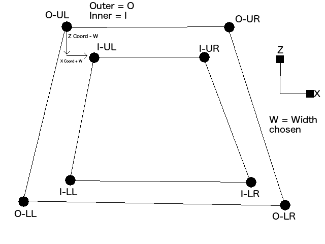
I want to create a mesh, that represents a "frame" of a trapezoid around this gameobject.
Creating the outer vertices works fine, but creating the inner vertices messes up (they are not evenly spaced away from the other vertices and the triangles I create seem to "flip" around and face the wrong direction and become invisible.
I have tried subtracting coordinates (but when the object rotates, these coordinates no longer are correct and the mesh looks messed up.
I have also tried scaling the outer vertices by a factor of 0.75, and this also seems to mess up too when the object is rotated.
How can I create this shape, without the rotation of the object throwing off the mesh creation?
It seems like you're trying to make a miter joint. The math behind it is discussed in one of the posts here. (Scroll down until you see the post with diagrams.)
It's a bit difficult to understand what you mean when you say "the triangles flip around and face the wrong direction" without code or screenshots of how it messes up.
You are probably setting the triangles clockwise, not counter clock wise(might be the other way around) You should flip the order in which you are adding the vertecies
Well I have created the mesh, and when the rotation is zero, it shows perfectly. But when it rotates, the vertices either dont stay in their correct relative locations (and hence the triangles get created in reverse) or the edges become very small/thin and become transparent.
The first image is the original mesh.
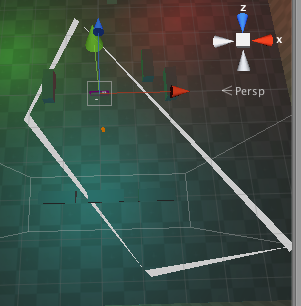
The second is the mesh generated when the object is rotated.
The third is when I raise the mesh in the editor and look at the underside of it. (it should be transparent but it's not as some vertices get converted to flipped triangles) 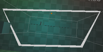

This is pseudo code unfortunately, however I feel like the Vector3.Slerp method should be useful here possibly:
 Vector3 OUL;
 Vector3 OLL;
 Vector3 OUR;
 Vector3 OLR;

 Float distIn = 0.5f; //how far in we come from the edge

 //go round clockwise
 Vector3 topEdge = (OUR-OUL).normalized*distIn;
 Vector3 rightEdge = (OLR-OUR).normalized*distIn;
 Vector3 bottomEdge = (OLL-OLR).normalized*distIn;
 Vector3 leftEdge = (OUL-OLL).normalized*distIn;


 Vector3 IUL = OUL + Vector3.Slerp(topEdge, -leftEdge, 0.5f);
 Vector3 IUR = OUR + Vector3.Slerp(-topEdge, rightEdge, 0.5f);
 Vector3 ILL = OLL + Vector3.Slerp(-bottomEdge, leftEdge, 0.5f);
 Vector3 ILR = OLR + Vector3.Slerp(bottomEdge, -rightEdge, 0.5f);

 Vector3[] verts = {OUL, OLL, OUR, OLR, IUL, IUR, ILL, ILR};

 Int[] triangles = {    0, 2, 4,
             4, 2, 5,
             2, 3, 5,
             5, 3, 7,
             3, 1, 7,
             7, 1, 6,
             1, 0, 6,
             6, 0, 4};
Maybe you can make use of that, it should do the rotation calculations for you if you do it all within the same coordinates, i.e. either all world coords, or all local coords.
The problem in my opinion is, that you offset the inside along the x and y axis of the world, not of the gameObject. Try ofsetting them by transform.up W + transform.right W or something.
As far as looking at it from the bottom, it is transparent because Meshes are only rendered on one side. You should add all vertecies and triangles again with inverted order, so the triangles are set the other way around.
I found a "reasonable" solution, where I use the opposite sides, create a direction vector, and multiple by my intended "width" of the frame I want. It is slightly to big width-wise, but it should work for now. My complication was trying to create a function that creates the inner vertices FROM the outer ones, without using coordinates.
 public static Vector3 TranslateDistanceBetweenPoints(this Vector3 start, Vector3 end, float distance)
     {
         Vector3 dir = end - start;
         Vector3 finalPos = start + (dir.normalized * distance);
         return finalPos;
     }

 public void generateMesh()
 {
                 //this assumes the "result" structure contains the outer vertices

                 innerResult.UpperLeft = result.UpperLeft.TranslateDistanceBetweenPoints(result.LowerRight,widthOfFrame);
         innerResult.UpperRight = result.UpperRight.TranslateDistanceBetweenPoints(result.LowerLeft,widthOfFrame);
         innerResult.LowerLeft = result.LowerLeft.TranslateDistanceBetweenPoints(result.UpperRight,widthOfFrame);
         innerResult.LowerRight = result.LowerRight.TranslateDistanceBetweenPoints(result.UpperLeft,widthOfFrame);

         //now use these points to create a mesh from the inner and outer points
         //UL
         //UR
         //LL
         //LR
         Vector3[] vertices = new Vector3[]
         {
             //outer
             result.UpperLeft,//0
             result.UpperRight,//1
             result.LowerLeft,//2
             result.LowerRight,//3
             //inner
             innerResult.UpperLeft,//4
             innerResult.UpperRight,//5
             innerResult.LowerLeft,//6
             innerResult.LowerRight//7
         };

         Vector3[] normals =
         {
             -Vector3.forward,
             -Vector3.forward,
             -Vector3.forward,
             -Vector3.forward,

             -Vector3.forward,
             -Vector3.forward,
             -Vector3.forward,
             -Vector3.forward
         };

         Vector2[] uv = new Vector2[]
         {
             new Vector2(1, 1),
             new Vector2(1, 0),
             new Vector2(0, 1),
             new Vector2(0, 0),

             new Vector2(1, 1),
             new Vector2(1, 0),
             new Vector2(0, 1),
             new Vector2(0, 0)
         };

         int[] triangles = new int[]
         {
             //upper
             0, 1, 4,
             4, 1, 5,

             //lower
             2, 6, 7,
             2, 7, 3,

             //left
             2, 0, 4,
             2, 4, 6,

             //right
             7, 5, 1,
             7, 1, 3
         };


         meshFilter.mesh.Clear();
         meshFilter.mesh.MarkDynamic();
         meshFilter.mesh.vertices = vertices;
         meshFilter.mesh.triangles = triangles;
         meshFilter.mesh.normals = normals;
         meshFilter.mesh.uv = uv;
 }
Did you check my answer, it does a similar thing using the outer points to interpret the inner points.
Yeah. It did help after I found my solution. Thanks for the advice.
